 Tooling Around
Taig Mill – Lights
When I saw Ikea's Jansjö LED lights, it occurred to me that they were just the right size to put some much-needed light in the shadow under the mill spindle. All I needed was a way to mount them where they would do what was needed and otherwise be out of the way. I chose to mount them on the ends of a bar attached to the rear of the mill column. I mounted a receptacle back there, too, with power to the receptacle being switched from the same switch box that contains the mill motor switch. All of this is described, below.
The Lights (Skip to "Receptacle Box".)

Each lamp contains one large, bright LED behind a focusing lens.

As purchased, the lights were attached to a metal base. Fortunately, they were threaded into the base, which made alternate attachment easy.
This light is available on a variety of bases and in at least a few colours. The two that I purchased for the mill were designed to be attached to a wall.

Here's the M6×1 thread after removal from the base. Traces of threadlock are still visible.

I covered the flex with some 10mm heat shrink. I'm not sure why I did this, but it may help stiffen the flex and keep out the grunge.

Each light came with a “wall wart” power supply.

The light is connected to the power supply via a plug that's molded onto the end of the wire. It made sense to leave this end of the connecting wire undisturbed and use the other end for a new connection.

The connector on more recent versions use a different connector. It appears to be a DIN loudspeaker connector. They're readily available, so you have other wiring options, if you're using one of these newer models. For example, you can more easily route the wiring through a small space by simply cutting off the existing connector and attaching a new one after the wiring is where you want it.
Receptacle Box (Skip to "Mounting Bar".)

A receptacle is required to supply power to the lights. I decided to mount it on the back of the mill column. This required the use of a spacer block to hold it off the column so the receptacle cover plate wouldn't be in contact with the column. The spacer block would also support the ends of the tubes that protect the light wiring.
This photo shows final drilling to size for a clearance hole for one of the 10-32 SHCS's that attach an electrical box to the back of the mill column.

After carefully aligning and clamping the spacer, transfer punches were used to mark the column.
Looking at this photo now, I see that the spacer is upside down. The rebate is for cover plate clearance, which means that it should be on the bottom. Good thing it didn't matter.

Here's a test fit of the electrical box, using the spacer.

Here are the SHCSs that hold the box in position. Holes in the mill column were tapped to accept the screws.

To keep swarf out of the box, the knockouts were hammered flat and the screw holes filled with rivets.
Mounting Bar

A mounting bar for the lights is mounted horizontally on the back of the mill column.
The first step was to mill a flat for the base of each light. This photo shows the bar set at a 45° angle in the vise, using angle blocks. The vise itself is tilted 35°. It would be better to use a three-way tilting vise, but I didn't have one, at the time.

Flats were milled for a light on two corners of the bar.

After the usual three-bit drilling sequence a mounting hole was ready for the tap.

Each hole was tapped M6×1 for the LED light.

The next step was to align the mounting bar parallel to the table, so a recess could be milled on the back of the bar.

An initial 3/8″ recess was milled, to the depth of the thickness of the cover. Then two recesses were milled 1/4″ wide and 1/4″ deep to provide room for wiring.
Note the use of the mill table stops to limit movement of the table. They were helpful in ensuring that the recess was long enough, and no more, as successive cuts were made to arrive at the correct depth.

While I had the bracket centred under the spindle, I marked the mounting holes.

A 1/8″ end mill cutter was used to mark out the full length and width of the cover. Except for the threaded corners at each end, a slot was milled on each side of the recess to the depth of the stiffening ribs on the cover.

A length of 1/2″ aluminum channel was used for the cover. The sides were mostly cut off, leaving stiffening ribs.

The stiffening ribs on the back of the cover were milled to their final height.
As you can see, the hold-down clamps interfere with the cut. However, since I was just bringing the ribs to the correct height, I simply moved the clamps from place to place as required to make the cut.
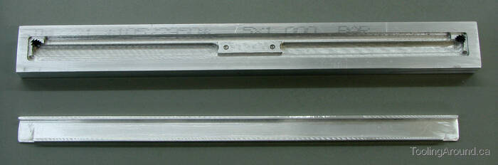
The mounting bar and cover, roughed out.
The cover's final fit was achieved by careful filing, then the cover was gently bowed, so the ends would stay down snug when the bar was mounted on the mill column.
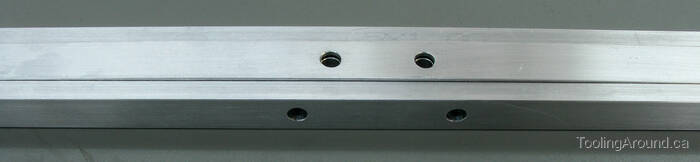
The holes in the cover are for the mounting screws. The holes in the bottom of the bar will accept the tubes that protect the wiring.

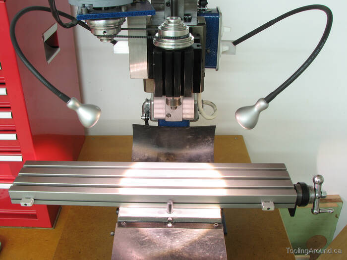
The parts are mounted and ready for wiring. The knurled ends of the stainless steel tubes are a tight press fit to the bracket and a sliding fit to the electrical box spacer.
As you can see, the power cord to the switch box has been removed, in preparation for new wiring.

The power supplies were plugged into the receptacle; the lighting wires were connected to the power supplies; and the free ends of the wires were fished up through the tubes and into the cavity in the mounting bar. The connections were made and now heat shrink covers my usual clumsy soldering job.
The original power cord now enters the new receptacle box. From there, a length of 14/3 wire brings power to the original switch box, where a double switch replaces the original single one. In other words, the original SPST switch was replaced by two SPST switches, in the same space. One switch controls power to the original motor receptacle and the other controls power back down the extra conductor, to the new light receptacle. I wired the upper switch to control the lights and the lower one to control the motor.

Buttoned up and ready to use.

This is the completed project. Well, almost – later, I mixed paint to approximately match the blue paint on the mill and painted the box and switch cover plate.