 Tooling Around
Cutting A Gear
My son repairs clocks. One of his customers had a Pequegnat clock that refused to run. It turned out that the problem was a gear that had split. As a result, the gear slipped on its arbor and the gap between the two teeth next to the split was too large, causing the broken gear to jam on the adjoining gear. In horology-speak, the pinion's leaves jammed on those of the wheel.
Having offered to try to help, I brought the broken gear home. After dismissing my initial thought that perhaps it could be silver brazed (which attempt would doubtless have resulted in a tiny, useless, melted brass blob), I decided to try making a replacement. The problem was that I had lots of very good information on making gears, especially for clocks, but no experience at all. After considering and rejecting a few different approaches, I proceeded as described here. My approach was not ideal. In fact, it wasn't very good at all, but it worked. If nothing else, perhaps it will encourage you to make the attempt, should you decide to try cutting a gear.
The Problem (Skip to "A Cutter".)

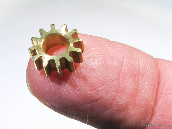
Here's the broken pinion. After many decades of use, it had finally given up.

As you can see, the pinion measures 0.398″ across the tips of the teeth.
A Cutter (Skip to "A Cutter Holder".)

As mentioned above, I did not choose an ideal method for cutting the gear. To avoid heat treating, I chose to simply grind a lathe tool to shape. It happened that I had no suitable material on hand for the preferred cutter.

The initial grinding provided some back rake, giving me a starting point.

The corners of the grinding wheel gave me a basic shape.

The roughly-ground cutter is taking shape, with some back rake, but no side rake. Because it will be cutting brass, no top rake is required.

Using an abrasive cutoff wheel in my Ryobi multi-tool, I carefully shaped the business end of the cutter, gradually sneaking up on the correct shape by matching it to the broken gear as I ground off just a tiny bit at a time. In the process, I also provided side rake under the tip.

Here's the completed cutter.

As you can see, the cutter shape matches the gap between two teeth. In this photo, the cutter and gear are sitting on pieces of material to bring their top surfaces to the same plane, so you can see the fit.
While refining the cutter's shape, I made this check repeatedly, using an Optivisor to help me check very carefully.
This is a good place to pause to point out some things that are “wrong” with this approach to making a cutter.
- I am working the entire time with a hardened cutter blank, which means that I have to grind the cutter, rather than, well, cutting it.
- Shaping the two sides of the blank means that I have to be very careful to make the sides symmetrical. If I had turned unhardened stock on the lathe, symmetry would have been guaranteed. I only got away with this approach because I was matching an existing gear, which served as a template.
- The cutter cannot be re-sharpened, because the flat, top surface must be ground to restore the edge. Because of the side and back rake, sharpening would change the cutter's shape.
- The cutter is much too long. Mounted in its holder, it's effective diameter is about 2.5″ somewhat more than double what I would have preferred.
- By design, the cutter has no top rake. This is fine for brass, but not suitable for harder materials, so this type of cutter is not ideal.
Despite these shortcomings, the cutter was made for one-time use, so I wasn't too concerned.
A Cutter Holder (Skip to "Cutting The Gear".)

A hole was drilled and bored to size to fit a shaft to the cutter arbor.

The shaft is a sliding fit.

The shaft was silver brazed to the arbor head.

First, I milled a slot in the arbor head.

Next, I drilled and tapped holes for grub screws.

The gear cutter is ready to use.
The slot is cut so as to place one side of the slot on the axis of rotation. By placing the “cutting side” of the cutter against this side of the slot, the cutter is correctly positioned relative to the axis of rotation.
Cutting The Gear (Skip to "The Result".)

This photo shows the workpiece after cutting has started.
There's a clue to what was going on, in the background of this photo. Clearly, all that waste was not produced by this small amount of cutting. The fact is that this was my third attempt to “get it right”.
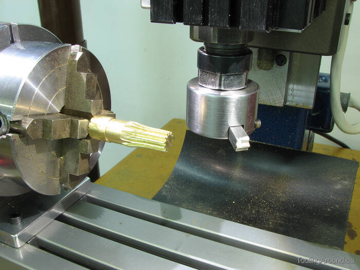
The work piece has begun to show the profile of the desired gear.
It would have been better to have supported the free end of the work piece. I got away without the support because I was cutting brass, which is soft, and also because I took light cuts (about 0.005″). Nevertheless, the more firmly the work piece is held, the smoother the cut will be.
The work piece would not have had to be so long, if I had used a cutter with a smaller diameter. That would have permitted cutting closer to the chuck jaws.

It's important to cut precisely on centre. Otherwise, the teeth will “lean” to one side or the other.

This is unconventional. Because the chuck is mounted on the rotary table, the chances are good that the workpiece will be off centre when I return the chuck to the lathe, to part off the gears. So, I milled a groove before removing the chuck, so as to have a reference surface for recentring the workpiece on the lathe.
Next time, I hope to devise a way to avoid this problem of repositioning the work.

This is how I got the work piece back on centre in the lathe. It was worth the trouble, as one pair of jaws had to be shifted 0.002″ and the other 0.003″, if I remember correctly. Maybe it wouldn't have mattered, but I wanted to do the best I could.

After starting the hole with a centre drill, I enlarged the hole so something less than the diameter of the clock's arbor.

Using the clock's arbor as a guide, I bored the hole to the depth of one gear, very gradually approaching the desired diameter. I wanted a close fit to the arbor, but not so tight as to risk splitting the new gear in the manner of the old.
After boring to the desired diameter, I used a cut-off blade to part the gear from the work piece. During the parting operation, I held an allen wrench in the hole to catch the gear as it fell off the work piece.
The reason I cut enough stock to make two gears is because I wanted a second chance, should I happen to make too large a hole on the first attempt. As it turned out, the first one was a success and now I have the second as a souvenir.
The Result

Here's the replacement gear, beside the broken one.

Here's the new gear. I very gently touched a fine file to it to chamfer the teeth as it spun in the lathe.
At this magnification, you can see that the leaves of the pinion lean slightly. It's not clear to me if it's because the cutter wasn't quite on centre or because the shape of the cutter was a bit off. Regardless, the gear does work, so it's okay.

Here it is, in its new home.


After all that, how did it turn out? Well, I'm happy to say that the clock has been running for a few weeks, as of this writing, so I'll call it a success. In fact, I delayed publication of this page until I heard that all was well.
Although this was a successful exercise, the next time I want to cut a gear, I expect to try making either a “proper” flycutter or, if the project warrants it, a four-tooth cutter.