 Tooling Around
Aligning A Top Slide
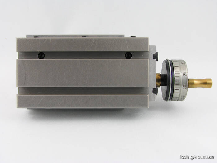
This is the Taig top slide. The underside, shown below, has a pair of T-nuts that fit into a slot on the cross-slide and mate with a circular dovetail on the top slide. You can see the circular dovetail under the capscrew that is used to draw the two T-nuts together. As the T-nuts tighten against the circular dovetail, they're drawn up against it, thereby clamping the top slide to the cross slide.

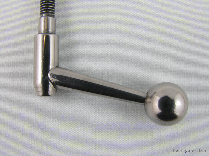
When using a top slide to turn a tapered work piece, sometimes the angle of the taper must be precise; other times, the exact angle is immaterial. For example, a ball handle normally uses a tapered shaft, but the diameters of the ends of the shaft are more important than the angle.
Here's a simple case, in which we want to turn a tapered shaft for a ball handle. We know the length of the tapered part of the shaft and the diameters at each end of the taper. We're going to make our cut from what will be the small end toward the big end, which is the end mounted in the chuck.
Now visualize the cut, concentrating on the radius of the material to remove. In this example, the tapered length of the shaft is 27 mm long; the diameter at the large end is 6.5 mm and the diameter at the small end is 3.5 mm. So, the difference in radius is 6.5 mm minus 3.5 mm divided by 2 equals 1.5 mm.
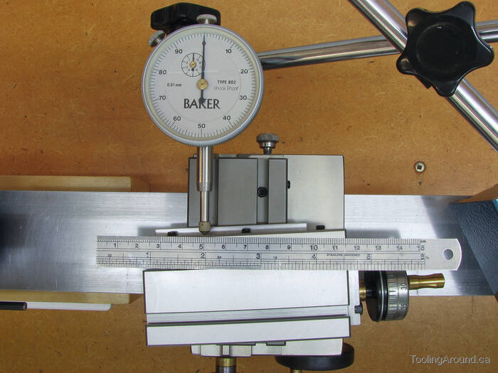
The photo shows a dial indicator reading from the back of the top slide and set at 90° to the lathe bed. The cross slide has been moved until the indicator reads zero. A rule is laying on the top slide, parallel to the lathe bed, with some convenient mark (50 mm) opposite the tip of the dial indicator.
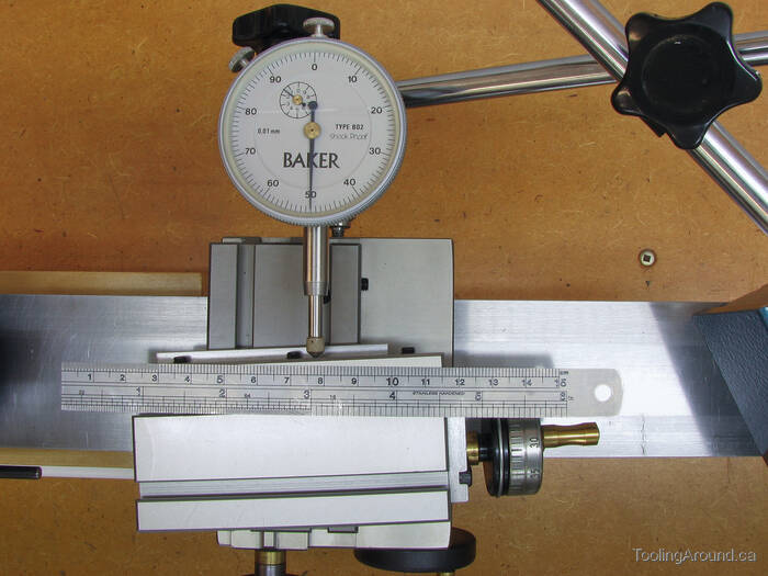
This photo shows that the carriage has been moved the 27 mm length of the taper, to the 77 mm mark on the rule. The dial indicator is reading 1.5 mm, which is the correct amount.
It is highly unlikely that the angle will be exactly what you want the first time you measure. It's a matter of trial-and-error adjustment as you work toward the measurement you want. For something like a ball handle, the tolerances are not particularly tight. For something like a Morse taper, they are.
It is certainly true that a weakness of this approach is that it relies on one's skill in measuring the length of the side, next to the rule. One way to reduce potential error is to measure over a greater distance. For example, instead of measuring a distance of 27 mm and looking for a displacement of 1.5 mm, measure over 81 mm and look for a displacement of 4.5 mm. By tripling the distance over which you measure, you effectively reduce an error to one third of its significance. Nevertheless, be as careful as you can when reading off the distance.
Because of the trial and error approach to the adjustments, it may make sense to leave the tension on the top slide screw somewhat less than tight until you get the angle right. If you do this, remember to tighten the screw after getting the angle right. Then check the measurement, again, to make sure that the angle didn't change because of tightening the cap screw.
Okay, that's the simple case, where you know the length of the taper and the desired change in radius. What if you know the desired angle, instead? The answer, of course, is to reduce this case to the simple one just described.
Here's a sketch that illustrates the solution.

What we know is the angle (θ) and we can choose some suitable length over which to make our measurement (α), so as to determine the distance (x) the indicator should measure over that distance. Here is the solution: x = α ⋅ tan θ
For example, if the angle is given as 7° and we decide to measure over a distance of, say, 70 mm, we should see a dial indicator deflection of 70 times the tangent of 7, that is 70 × 0.12278, which equals 8.60 mm.
Here's a calculator that you can use to determine the value of x, given an angle and a length. Enter the length over which you want to measure and the desired angle, and the offset will be calculated. You can enter the number of degrees using a decimal point, such as 7.5 or use degrees, minutes and seconds, such as 7° 30′ 0″, whichever you prefer.
The number of degrees, minutes and seconds will always be summed to arrive at the angle, so you could even use the odd, but acceptable, 7.25° 15′ 0″ notation. Similarly, 7.5° could be specified as 6° 90′ 0′, although I can't imagine why one would do so. Regardless of how you enter the angle, when the appropriate rounding and conversion to decimal has been done, the angle must be less than 90°.
| Length (α) in any desired units |
| Taper Angle (θ) ° ′ ″ |
| The calculated result (or an error message) will appear here. |
Why support an angle specified in degree, minutes and seconds? When I checked Wikipedia for Morse taper information, that's how the angle was specified. So, I decided to add the provision to the calculator.