 Tooling Around
Part 1 – Speed Controller
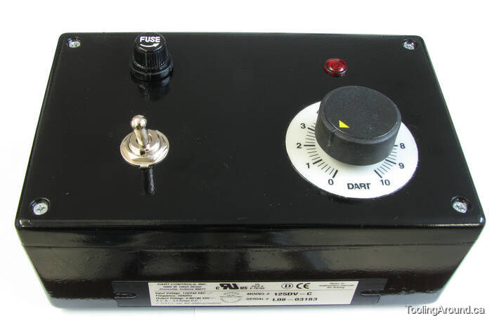
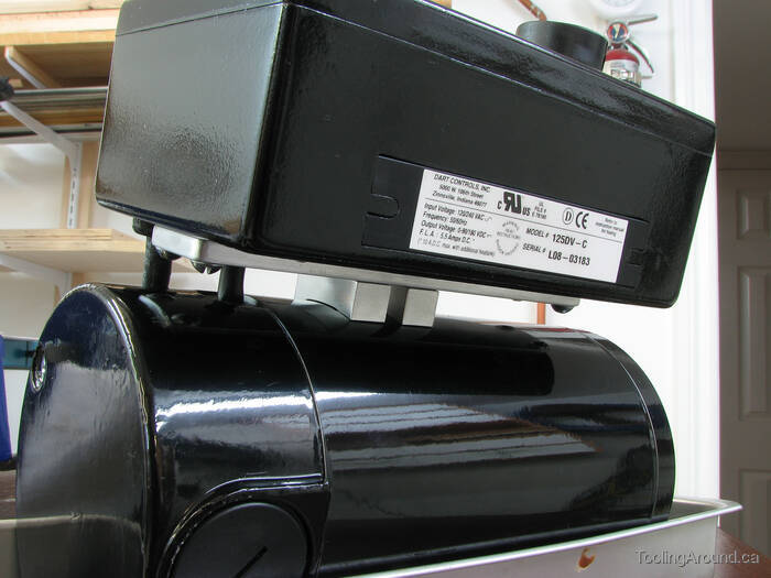
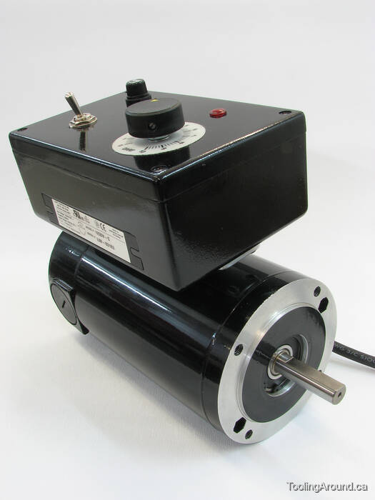
The speed controller is a Dart Controls 125DV-C. The box used to house the controller is a Hammond Manufacturing 1594ESGY. (Had a black box been available where I bought my gray one, I wouldn't have had to paint it.) In addition, I purchased a power switch, fuse, fuse holder, pilot light, cord strain relief, power cord and plug.
The motor is a continuous duty Bodine 130VDC motor, rated at 1/3HP. Since my Dart controller will put out no more than 90VDC, the motor will certainly be under-stressed.
This particular motor is no longer available from Bodine Electric Company, but 42A Series motors are very similar.
Controller Box (Skip to "Controller Mount".)
The first part of the job was to prepare a box that would hold the speed control circuit board and associated components.
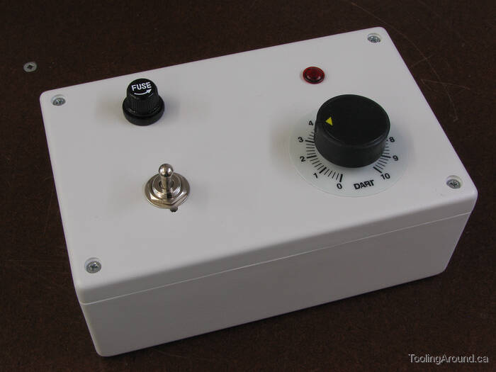
To start, I marked out and drilled four holes in the top of the box. Well, the one for the fuse holder isn't round; two flat sides keep the holder from turning in the hole. Then I tried this test fit. The toggle switch is a SPST power switch. Above it is a fuse holder containing a Littelfuse 6A 250V fast-acting ceramic body fuse. To its right is a 115V red neon pilot light. Below that is the speed control potentiometer that came with the speed control. The adhesive-backed disk with the gradations is attached under the potentiometer's knob.
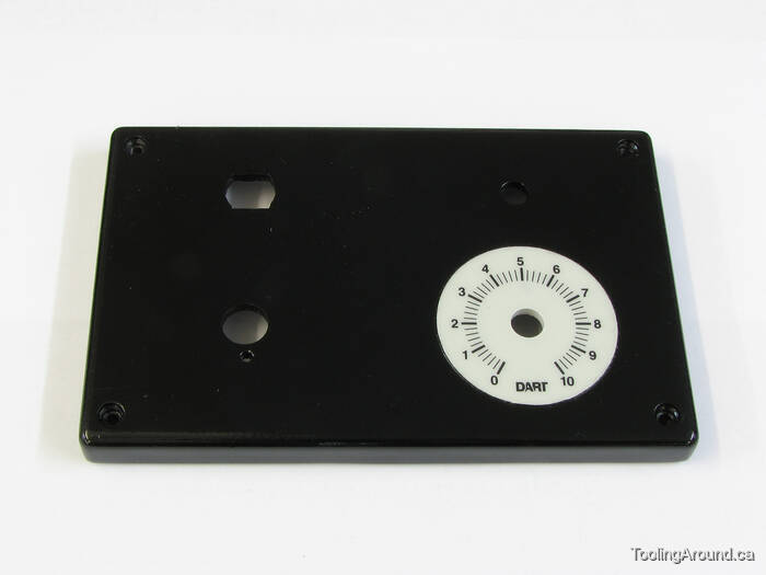
After masking the the plastic disk with the gradations, I spray painted the box top (and the bottom, too).
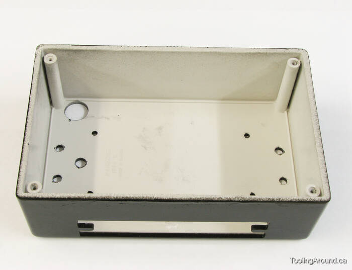
Here's the box bottom. The odd opening in the side was cut a bit undersize using the mill. Because of the setup, the plastic tended to flex, so I didn't attempt the final fit. Instead, I took advantage of the mill's capabilities to ensure that the sides of the opening were aligned precisely. Final fitting was done using files.
On the bottom side of the box, I drilled mounting holes and a larger hole for the power cord grommet.
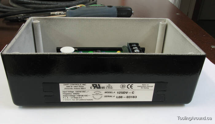
Presumably, when the motor is working hard, the controller will produce more heat. It has a good heat sink, but one would expect to be more effective if the heat could get out of the box, so I decided to get at least part of it into the air by cutting that form-fitting opening in the side of the box. Will it make any real difference? Probably not, but it does no harm and it seemed like a good idea at the time.
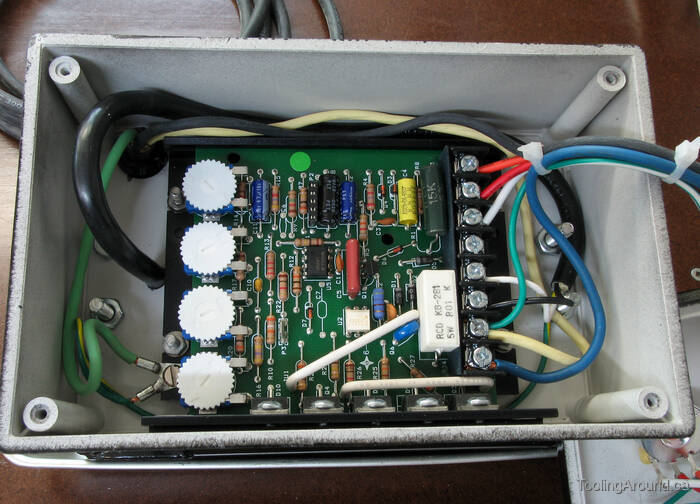
Here's the controller, attached to the box bottom using standoffs and wired up and ready to go. The four white knobs on the left are for adjusting the behaviour of the controller. You can read about it on the manufacturer's web site. It took some experimentation to get the adjustment right.
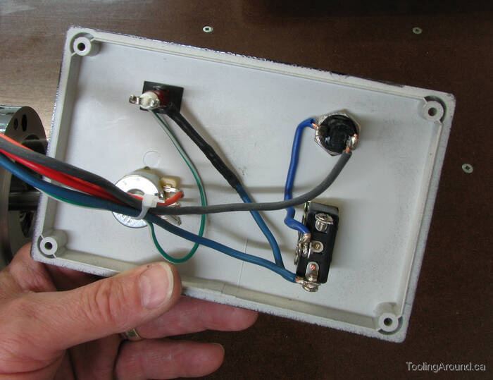
This is how I wired the other components. The circuit is straightforward. Please ignore the wire colours – I made no attempt to follow any standard colour coding, but just used what I had in my scrap box.
Controller Mount
The next step was to make mounting hardware to attach the speed control box to the motor.
This photo is mostly interesting because of the workholding. These two pieces of aluminum will be used to mount the controller box to the motor. In this photo, the two screws holding the work pieces to the aluminum angle were threaded just for workholding. Later, they will be clearance-drilled for the screws that attach these mounts to the motor, which has two threaded holes for the purpose. Two other holes in each piece will be threaded to attach the box to these standoffs.
By attaching the standoffs to the aluminum angle, the two surfaces that will eventually be attached to the contoller box are held in the same relationship they will have, later. The opposite surfaces, where the line shows where the saw is about to trim them, are out in the open where they can be machined. The short piece of steel bar underneath holds them up clear of the longer piece of steel bar, so the standoffs can be machined right down to their edges. Finally, the longer steel bar can be gripped in a vise, as shown here, or fastened to a rotary table, as shown in the next photo.
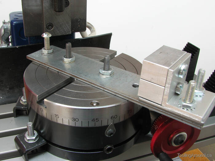
Here's the sort of thing you do when your rotary table is too small to allow you to cut a desired radius. In this case, the radius must match the radius of the motor, so the standoffs will fit properly.
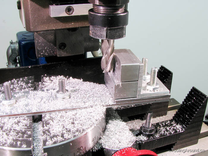
An arc is cut on the standoffs, to match the motor. After this cut was made, all the way to the bottom of the stacked standoffs, the mill table was adjusted to move the spindle a little farther away from the centre of the rotary table. In other words, the radius of the cut was increased. Then a short arc was milled between the edges of the standoffs, leaving, in effect, a foot at each end of the original arc. OK, that's not easy to explain, but it's clear in the next photo.
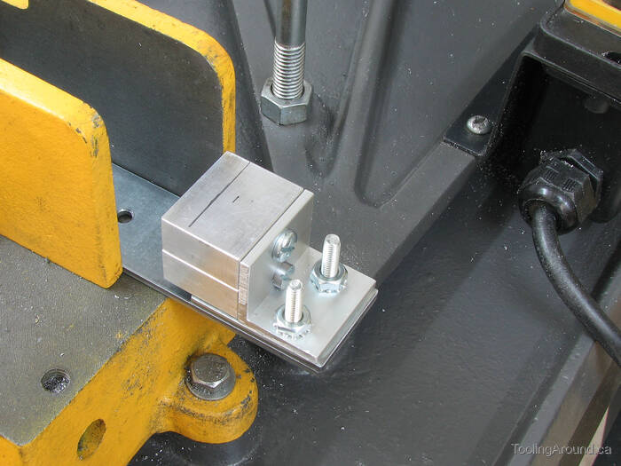
Here's the controller, sitting on the motor. As you can see, the power cord from the controller to the motor extends straight down through the bottom of the box and into the motor.
You can see the small gap under the standoffs, where the larger radius milling removed a bit of extra material, leaving the “feet”. This avoids the potential problem of the standoffs rocking on a high spot.
The box is attached to a thin aluminum bar. The bar, of course, is attached to the standoffs. This use of the bar avoids attaching the box at points that are relatively close together. To do so may have induced stresses in the plastic box. Although it is sturdy, this avoids a potential weak spot. It also means that the box is attached near its ends, which puts the fasteners beyond the edges of the controller board. Less potential for sparks, that way. You can see where the screws come through the box bottom, in the earlier photo of the controller board in the box.
So, the controller is firmly attached to the motor, but now the motor needs to be mounted on something.