 Tooling Around
Lathe – Boring Bar
There are two ways to use a lathe for boring operations.
- The most common one is to mount a boring tool to the cross slide, fix the workpiece to the spindle and advance the boring tool into a hole in the spinning workpiece. For example, see Boring Tool Holder.
- The other way is to mount a cutting tool in a boring bar, mount the boring bar between centres, fix the workpiece to the cross slide, with the boring bar projecting through a hole in the work piece, and advance the workpiece past the spinning cutter in the boring bar.
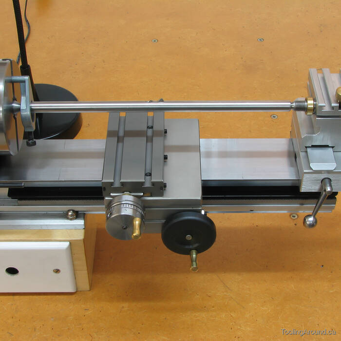
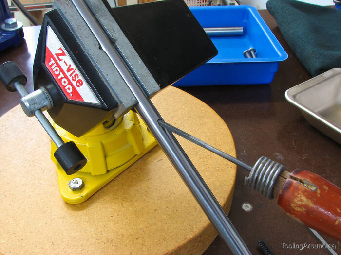
This page describes the latter approach. This particular boring bar was made when I was making my Bodine motor mount. Here's a picture of it being used.

Now, the simple truth is that a long bar will flex under load and the boring bar must be at least double the length of the hole being bored plus clearance for the cutter and such clearance as may be required for movement of the carriage toward the headstock or tailstock. In the case of this particular boring bar, the hole was relatively long. Further aggravating the problem of flexing, the hole diameter was small, relative to its length. As a result, I ended up with a boring bar that is 9″ long, with a diameter of 0.375″, a ratio of 24:1. To some extent, the flexing doesn't matter, as it is customary to end with a spring cut (or two, or three). However, flexing can facilitate chatter, which was my main concern.
The bar, drilled to mount on centres.
The diameter of the bar is too great to allow it to pass through the spindle, so I held it in a chuck with a steady rest to support each end, in turn, using a centre drill to make the holes.
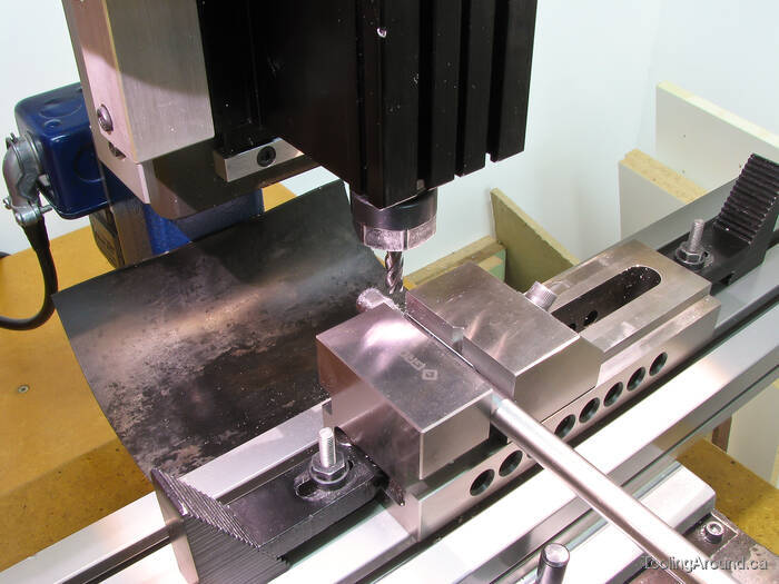
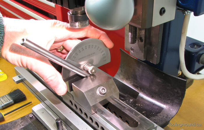
Milling a flat.
The movable jaw of the vise has a V-slot, which is being used to hold the bar in a horizontal position.
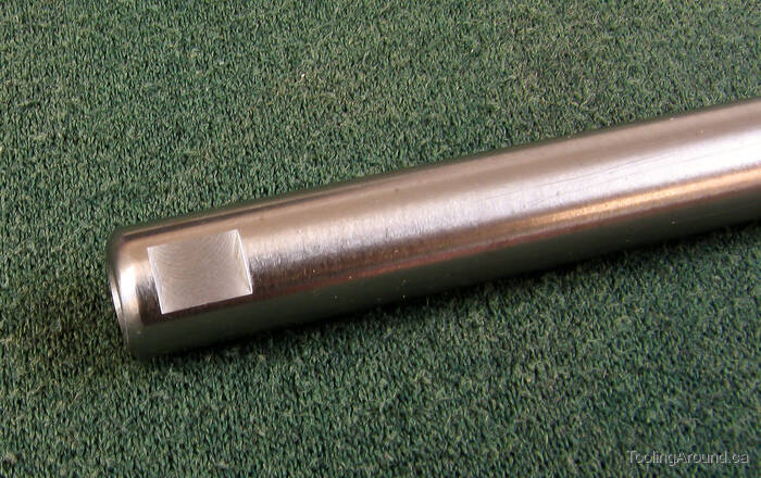
The flat for a lathe dog.
Generally speaking, it's better to use a flat instead of tightening a set screw against a shaft. This avoids raising a burr. Admittedly, a burr wouldn't really matter, in this case, nevertheless a flat is good practice. In addition to avoiding a burr, it provides a more positive grip.
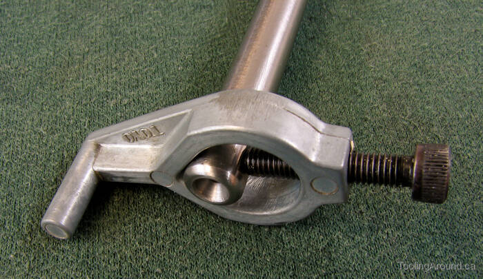
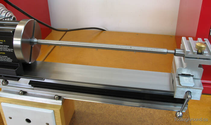
The lathe dog, mounted on the bar.
You can see the print showing that this lathe dog is a Toyo accessory. It came with my Toyo ML-210 lathe.
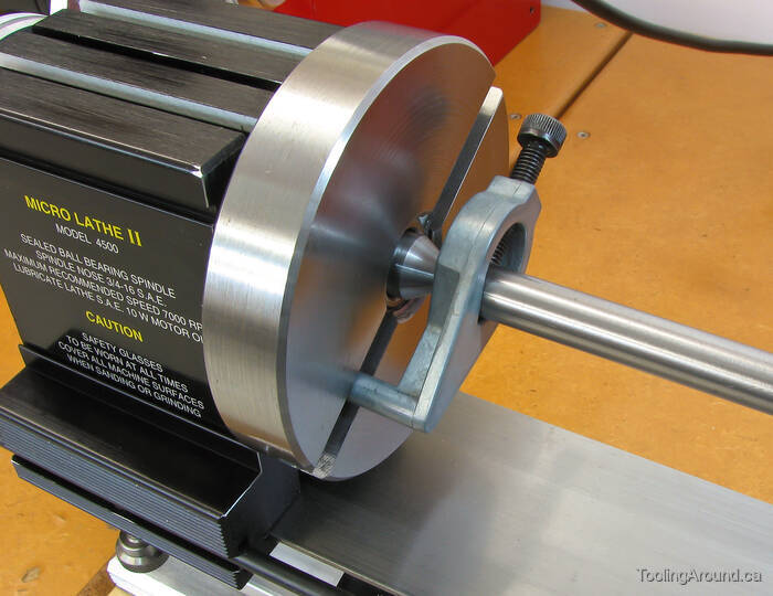
How the lathe dog drives the bar.
The boring bar is supported on a dead centre in the lathe spindle. The cap screw attaches the lathe dog to the boring bar. The “leg” of the “dog leg” engages the slot in the face plate.
This is definitely not the best way to hold the bar, so I took a tight grip. The problem is that machining forces could cause the work piece to shift in the vice, with unpleasant results.
A much better way to hold the work piece is to use a three-way tilting vise. Unfortunately, I didn't have one, at the time. However, experiences like this one provided the incentive to acquire one.
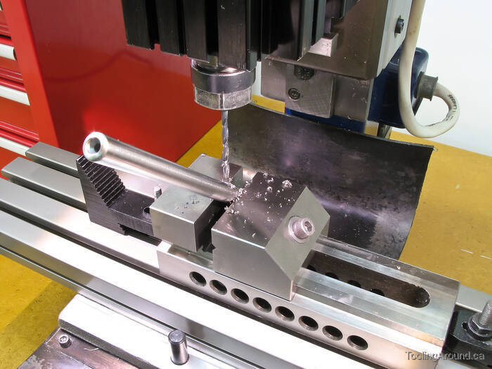
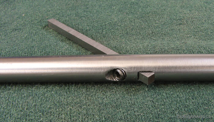
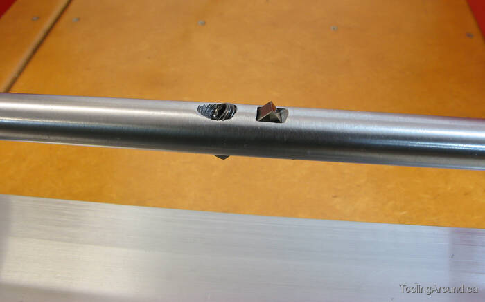
I milled flats and then drilled holes at 45°, one for the tool bit and one for a grub screw to hold it. As usual, I started with a centre drill, followed by a twist drill. The reason for milling flats is to give the drill bits a nice, horizontal surface to cut. Otherwise, they would tend to slide down the work piece as pressure is applied. Well, they would only slide a little, actually, followed by the sound of a drill bit snapping.
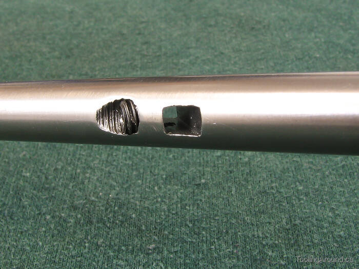
Making a round hole square.
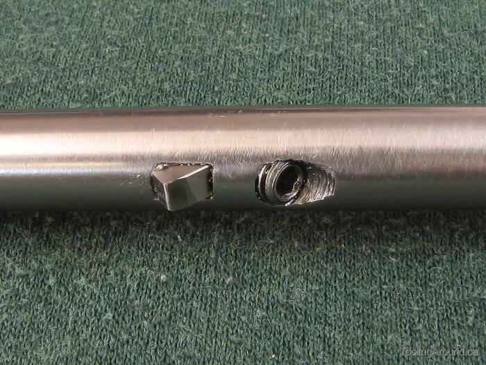
Looks like a good fit for a 1/8″ tool blank.
Not bad for a bit of hand filing.

The tool bit. The cutting corner is slightly rounded to produce a smoother cut.
Here it is, mounted in the boring bar.
The completed boring bar, ready to use.
So, how well does it work? I have mixed feelings. It did work reasonably well, except for chatter. I think there are two reasons for the chatter.
First, the boring bar length-to-diameter ratio of 24:1 was asking for trouble. Given any irregularity in the cut, the bar would flex away and then spring back with a bit of extra force, much like a truck wheel bouncing over washboard on a gravel road. Since, at the beginning, the hole being bored is almost by definition irregular (otherwise, why bore it?), the depth of cut will indeed vary, especially when boring just commences.
Second, I think the cutting geometry is incorrect. Try to visualize an imaginary line drawn through the cutting edge and its centre of rotation. Never mind, here's a sketch.

Looking at this drawing, it's clear that the cutter presents negative rake to the workpiece. Too bad I didn't make this sketch prior to grinding the cutter. I made the drawing after experiencing chatter, as I tried to figure out what went wrong. Next time I need to use it, I'll make a change to the cutter geometry and update this page to report on the difference it makes.
Third, the cutter was tricky to adjust. When I used it to make the pedestals for the Bodine motor mount, it was a matter of trial and error. I was trying to make a motor mount, after all, not meaning to be too distracted by making a boring bar. So, I simply used my dial calipers to measure the distance between the cutting tip and the opposite side of the boring bar. Whatever the measurement, I simply loosened the cutter's grub screw, moved the cutter the amount I hoped was correct, measured again and compared the before and after measurements. Repeat until the desired measurement is obtained. Practically, this meant that I removed the bar each time I wanted to make the measurement. This is truly tedious. Perhaps I'll make a simple jig to make it easier. Perhaps.