 Tooling Around
Part 5 – Base & Motor Plate
The base is simple: just a rectangle of 3/8″ aluminum plate. Except for careful location of the holes for attaching the pedestals, the work is mostly cosmetic. The base was attached to the workbench by 1/4-20 large head bolts, typically sold as knock-down furniture hardware.
The motor plate is made from 1/4″ aluminum plate. As much as anything else, it pleased me that I remembered to position the mounting holes for the motor so the speed controller ended up tilted toward the lathe operator.
Base Plate (Skip to "Motor Plate".)
The edges were milled nice and straight.
A chamfering cutter was used to make a nice bevel on each edge.
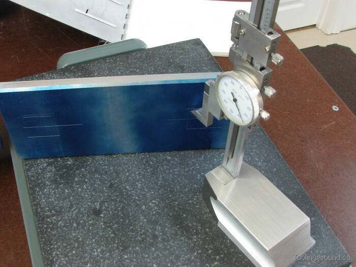
After spraying some toolmaker's ink on the plate, I used a height guage on a surface plate to mark out the location of the mounting holes. It was important to place them accurately, in order to have the pedestals aligned correctly.
Purists will suggest using the mill to position the holes and they would be correct. Nevertheless, this is another approach and it was successful.
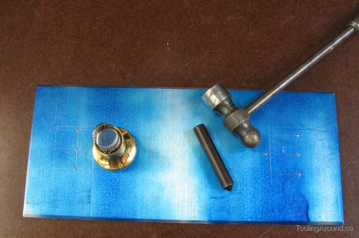
I used an optical centre punch to mark the positions to be drilled. In this photo, the optical post is inserted, to position the tool accurately over the intersection of two scribed lines. It's remarkable how much light gets down the lucite pipe and how well it magnifies the lines, making placement easy.
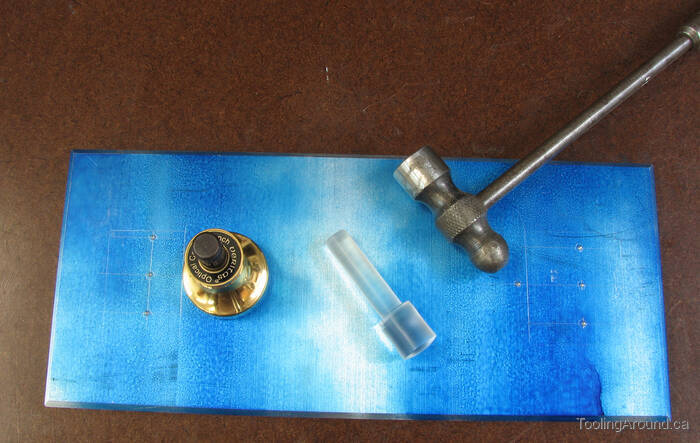
The optical post has been removed and the centre punch inserted, to dimple the position for a hole.
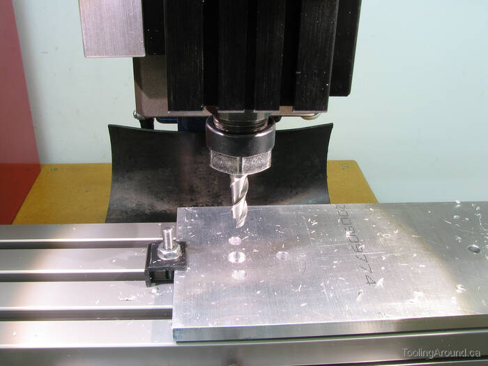
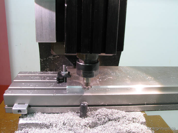
The holes were drilled, using the mill. In this photo, I'm counterboring the underside for one of the socket head cap screws that will hold the pedestals to the base.
Motor Plate
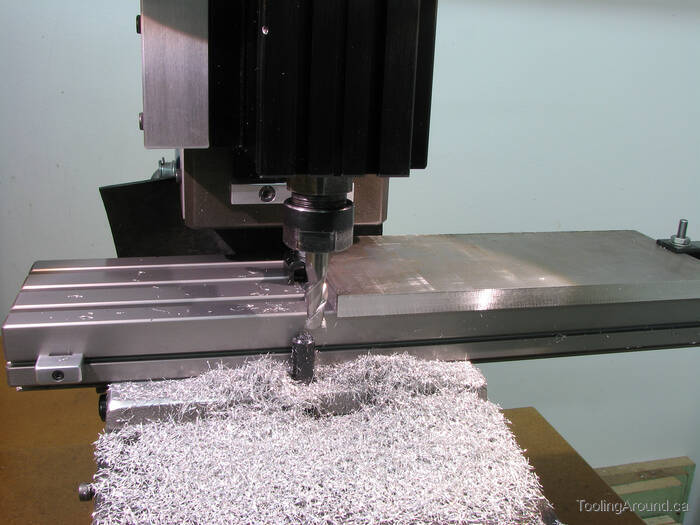
After marking out the motor plate's shape, I attached the plate to the mill table, sitting on a couple of precision spacers, and milled each straight side. The plate was set up twice, each time aligning the edge to be trimmed, so it would be true to the mill table.
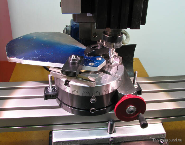
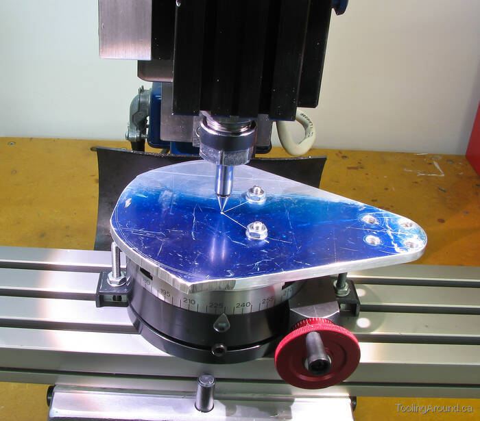
After centring the small end of the plate on the rotary table, I drilled four holes for the screws that will fasten the plate to the hub on the mounting shaft. Then I milled the arc to match the hub and meet the straight edges of the plate in a fair curve. It was convenient to stop the milling just short of the straight edges and use a file to form the transition from the curve to the straight edge. The human eye is very adept at determining a pleasing result and this is, after all, a question of appearance, not precise fit.
The plate is fastened to the rotary table using two threaded rods screwed into T-nuts. The holes are in the waste part of the plate. There's nothing special about the location of the holes, except that I positioned them where they are so I could move the workpiece along either of two slots that are at right angles to one another in the rotary table's face plate. This gave more freedom of movement when centring the plate on the table.
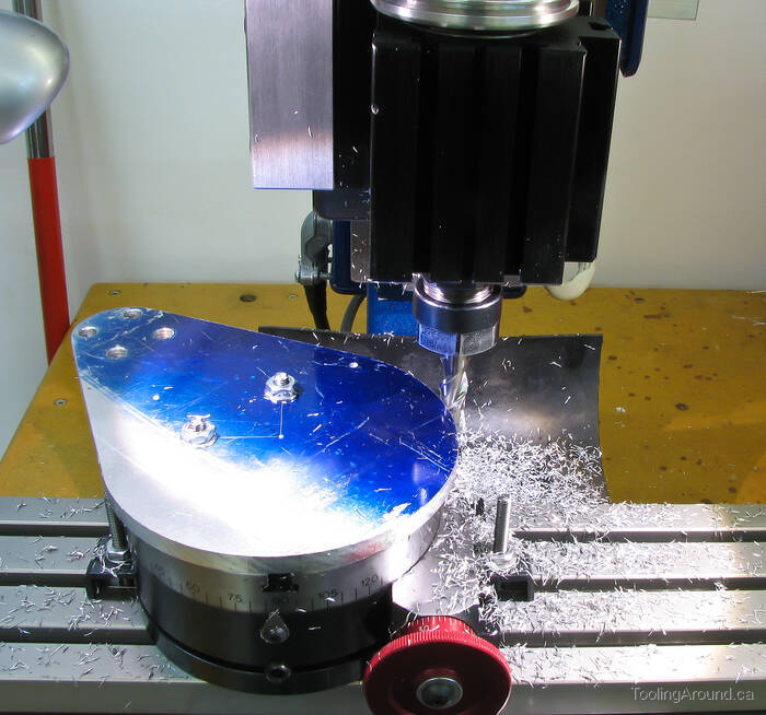
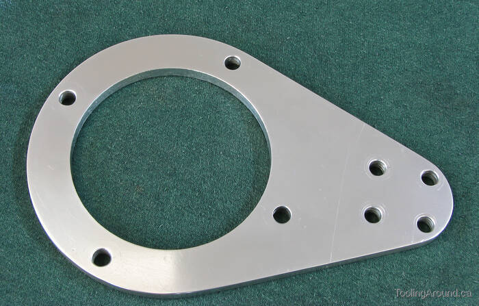
As with the small end, the large end was trimmed to form a nice curved transition to the straight sides.
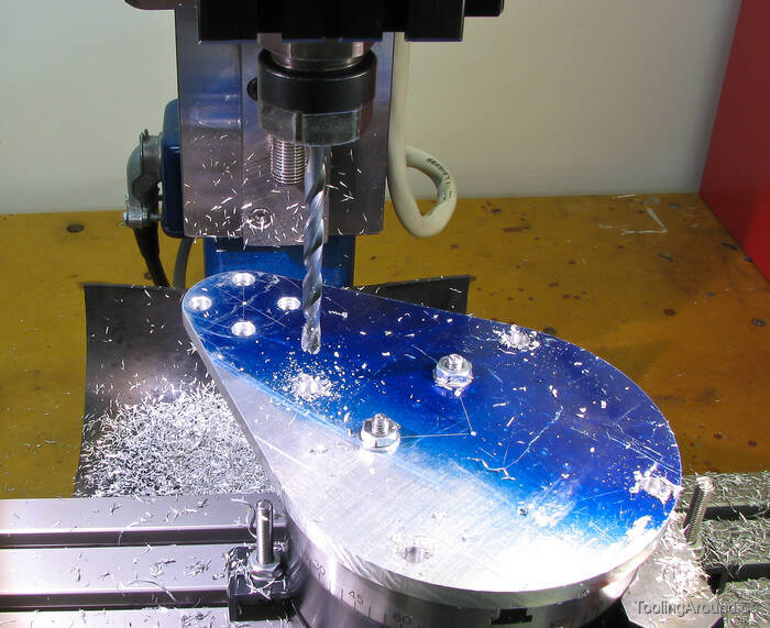
Four clearance holes were drilled to accept 1/4-20 screws that will hold the motor on the plate, or is it the other way around?
The only trick was to remember to drill these so the motor controller would be at the desired angle when the motor was installed.
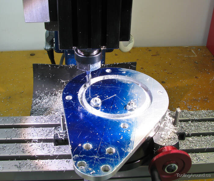
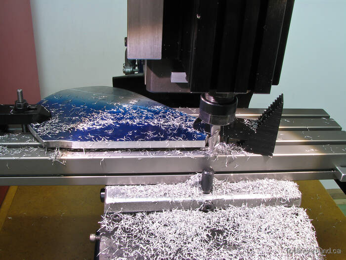
To cut the hole for the motor, I just cranked the rotary table around as I lowered a cutter into the plate. As the cutter started coming through the plate in places, I stopped milling and lifted the part off before it came loose, thereby avoiding the risk of a jam. After de-burring the edges, it was essentially finished.
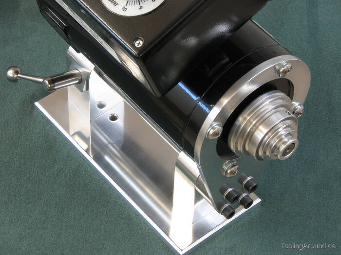
I took care with the diameter and it paid off with something just short of a press fit with the motor. It doesn't exactly slide on, but no tools are needed to press it on, just hand pressure.
After the machining was done, I treated it to a bit of a polish. My usual technique is to use wet/dry paper on a piece of plate glass. The glass is a bit larger than a sheet of abrasive paper and about 1/2″ thick. I put it on a piece of that rubbery drawer liner material, on a cookie sheet. I use a spray bottle to keep the paper wet and just rub the part on it until it looks OK. I usually start with 800-grit paper and go finer from there, depending on the finish I want. Then I treat it to some metal polish and that's it. It's pretty bright at first, but after a while it's just a nice smooth, dull colour.
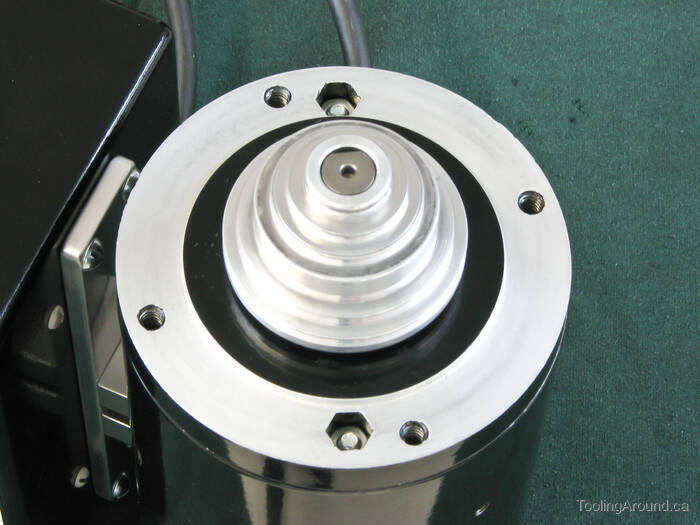
It isn't quite clear in this photo, but if you look closely, you can see that the black part of the motor next to the pulley is raised from the machined flat circle that surrounds it. This raised part is a close fit to the motor mount plate.