 Tooling Around
Thread Cutting Attachment
As on many other lathes, threads may be cut by engaging a gear train that turns the lead screw in concert with the spindle. The choice of gears determines the overall ratio between spindle and lead screw revolutions and that determines the distance between adjacent threads.
There's more information on this page than most people will care to see. However, bear in mind that this accessory is no longer available for purchase. My hope is that it may help you make your own, if you're so inclined, as thread cutting adds an important capability to the lathe. If you're interested in doing so, download the PDF drawing provided at the end of the page and you will find measurements to assist you.

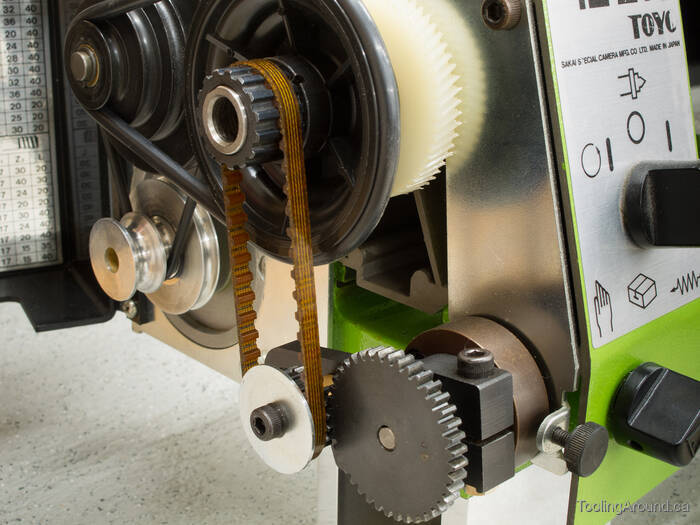
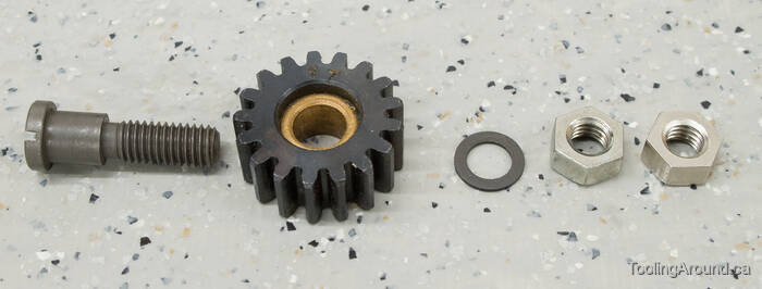
To start, here's a photo of the components that comprise the Toyo thread cutting attachment. The components are arranged as they are in the illustration in the Toyo instruction manual.
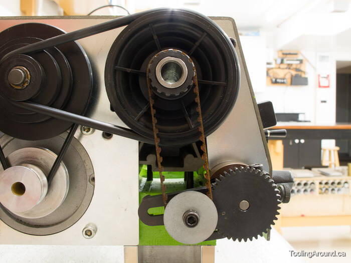
Starting at the top of the three gears (collectively, the “change gears”), the topmost is the main spindle gear, which is attached to the end of the spindle, next to the pulleys. In keeping with the naming convention in the Toyo instruction manual, we'll call this gear W.
The cogged belt carries the drive from the spindle to the next gear down.
The second gear is actually a pair of gears and the other gear in the pair carries the drive down to the bottom-most gear. We'll call this gear pair Z1 and Z2. To the left and right of this gear pair you can see the plain bronze bearing and the hardware that fixes it to the gear bracket.
The bottom gear is attached to the lead screw (via the dog clutch) and thereby moves the carriage in concert with the spindle, allowing you to cut threads. We'll call this gear L.
The gear bracket, sometimes called the “banjo” is to the right of the gears.
Finally, the bearing block is to the right of the gear bracket.
Okay, that's a summary of the components, which are described in detail on the rest of this page. Rather than describe thread cutting thoroughly, I encourage you to read about it elsewhere, if you would like more details. This page is just about the Toyo thread cutting attachment.
Gear Train (Skip to "Bearing Block and Gear".)
As described, above, a set of change gears turns the lead screw in some ratio, relative to the spindle. The choice of change gears determines the thread that can be cut. The following table, from the Toyo manual, shows gear trains used for various thread pitches.
| Pitch | W | Z1 | Z2 | L |
| 0.2 | 15 | 30 | 16 | 40 |
| 0.25 | 15 | 30 | 20 | 40 |
| 0.3 | 15 | 30 | 24 | 40 |
| 0.35 | 15 | 30 | 28 | 40 |
| 0.4 | 15 | 30 | 32 | 40 |
| 0.45 | 15 | 30 | 36 | 40 |
| 0.5 | 15 | 15 | 20 | 40 |
| 0.6 | 15 | 15 | 24 | 40 |
| 0.7 | 15 | 15 | 28 | 40 |
| 0.75 | 15 | 15 | 30 | 40 |
| 0.8 | 15 | 15 | 32 | 40 |
| 0.9 | 15 | 15 | 36 | 40 |
| 1.0 | 15 | 15 | 20 | 20 |
| 1.25 | 15 | 15 | 25 | 20 |
| 1.5 | 15 | 15 | 30 | 20 |
The No. 3413 thread cutting attachment includes gears for cutting the nine thread pitches from 0.5–1.5 mm. An additional gear set, No. 3412, provides gears to cut six additional pitches from 0.2–0.45 mm.
Ready for a little simple math? Me neither, but here goes. Via the cogged belt, W drives Z1. Because Z1 and Z2 are joined, Z2 then drives L. So, this means that we have a double reduction gear, with the ability to control the ratios between each pair of gears. The lead screw pitch is 1 mm, so, if both gear ratios are 1:1, the resulting carriage movement will be 1 mm. You can see this in the table for thread pitch 1.0 mm, where the first two gears each have 15 teeth and each of the second two have 20 teeth. The first ratio is actually W divided by Z1 and the second is Z2 divided by L. Multiply these two ratios together and, given the lead screw's 1 mm pitch, we know that the carriage will move 1 mm for each revolution of the spindle. For another example, consider the table entry for a 0.3 mm pitch. Using “computer notation”, the formula is W / Z1 * Z2 / L, which is 15 / 30 * 24 / 40 = 0.3.
The No. 3419 thread cutting attachment was provided for cutting inch threads, as shown in the following table. Now, it has to be said that, since 1 inch equals 25.4 mm, it follows that a 127-tooth gear has to be in the train somewhere, to cut precise inch threads. However, there's no 127-tooth gear in the train, nor is there physically room for one. Using the formula described previously, according to the table, the pitch (in mm) for 16 TPI is 18 / 17 * 30 / 20 = 1.588235 and a bunch more digits of decreasing significance. Since one thread at 16 TPI is 0.0625 inches and that's equivalent to 1.5875 mm, one must conclude that inch threads are a close approximation when cut on this Toyo lathe. For many purposes, close is just fine.
The following table is also from the Toyo manual and shows gear trains for several numbers of teeth per inch. I've added three columns showing the pitch that corresponds to the desired thread pitch, the pitch that will be produced by the gear train and the size of the error, all in millimetres. As you can see, the differences are very small, indeed.
| TPI | W | Z1 | Z2 | L | Desired Pitch | Actual Pitch | Pitch Error |
| 16 | 18 | 17 | 30 | 20 | 1.5875 mm | 1.5882 mm | 0.0007 mm |
| 18 | 18 | 17 | 40 | 30 | 1.4111 mm | 1.4118 mm | 0.0007 mm |
| 20 | 18 | 17 | 24 | 20 | 1.2700 mm | 1.2706 mm | 0.0006 mm |
| 24 | 18 | 17 | 20 | 20 | 1.0583 mm | 1.0588 mm | 0.0005 mm |
| 32 | 18 | 17 | 30 | 40 | 0.7938 mm | 0.7941 mm | 0.0003 mm |
| 40 | 18 | 17 | 24 | 40 | 0.6350 mm | 0.6353 mm | 0.0003 mm |
| 48 | 18 | 17 | 20 | 40 | 0.5292 mm | 0.5294 mm | 0.0002 mm |
| 56 | 18 | 17 | 15 | 35 | 0.4536 mm | 0.4538 mm | 0.0002 mm |
| 64 | 18 | 17 | 15 | 40 | 0.3969 mm | 0.3971 mm | 0.0002 mm |
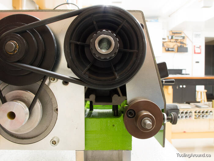
Bearing Block and Gear (Skip to "Gear Bracket".)
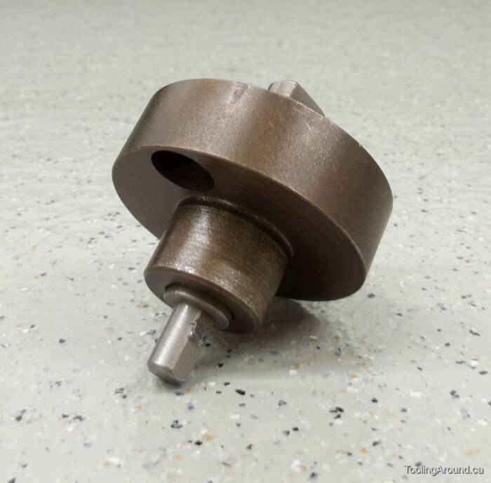
The bearing block is the support for the thread cutting attachment and contains the fixed half of the dog clutch that engages the lead screw.
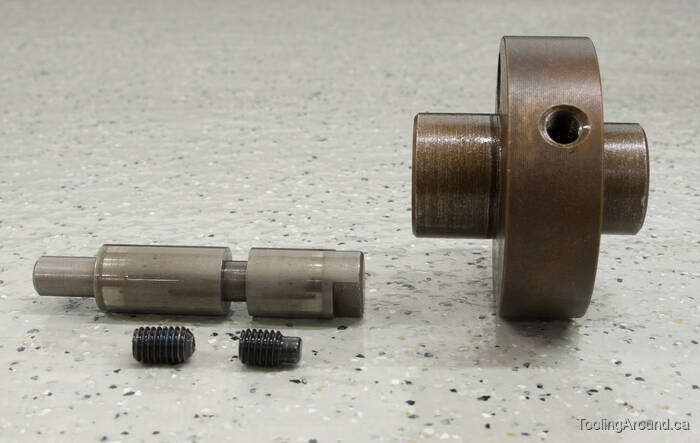
The bearing block is made of steel, bored to hold the non-sliding side of the dog clutch. The small end of the dog clutch shaft has a flat for a grub screw that fixes gear L to the shaft.
The grub screw is turned down to form a pin. This grub screw is screwed down far enough for this pin to protrude into the groove in the shaft, thus keeping the shaft from sliding along in the bearing while still allowing it to spin. The other grub screw is screwed into the same hole, where it's tightened against the head of the first grub screw, thereby locking it in place.
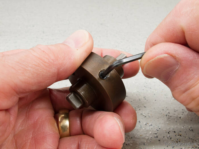
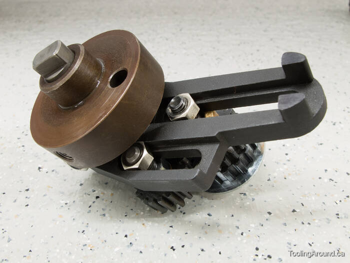
When tightening the second screw against the first, the locking screw tends to turn the first one too far into the hole. I've found that this tendency can be corrected by holding the assembly as shown, with one finger pushing the shaft against the pin (inside the bearing). This provides just enough of a grip to keep the first screw from turning and lets you tighten the second one. It may take a couple of tries to make the adjustment.
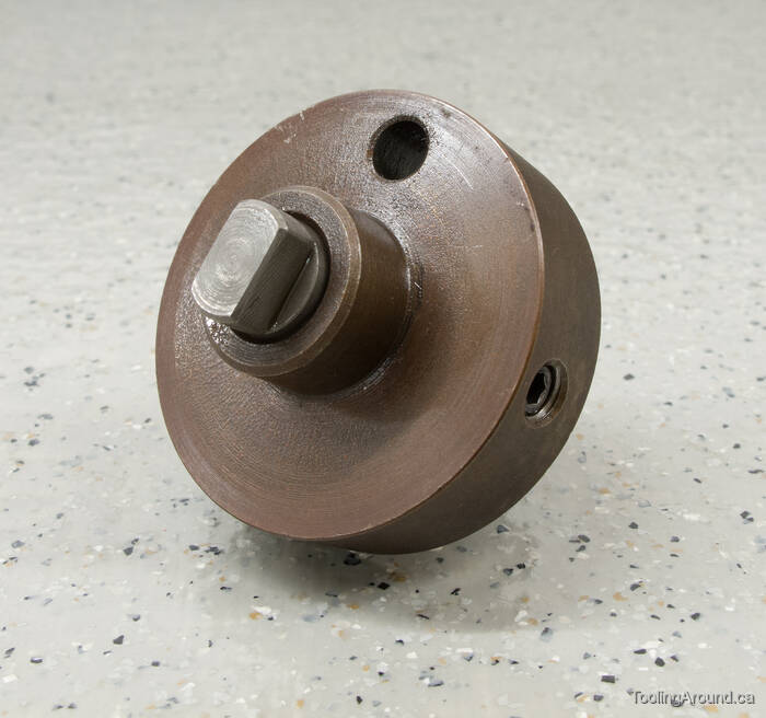
This end is inserted into the hole in the headstock, where the movable part of the dog clutch can engage it.
Gear L will be attached to this small end.
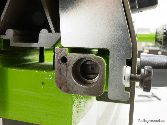
There's the movable part of the dog clutch and a tapped hole for the mounting screw.
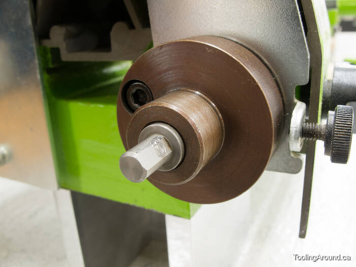
The bearing block is attached using an M5 × 0.8 SHCS, 15 mm long.
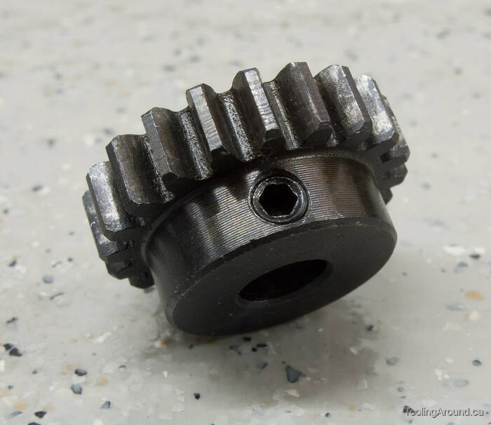
This is gear L, with 20 teeth.
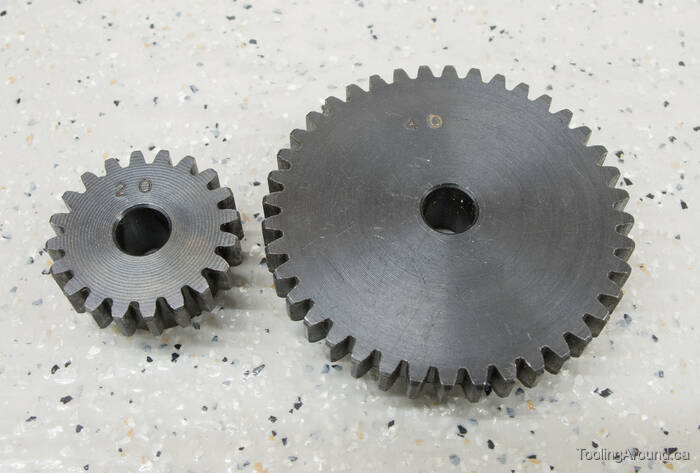
Thread cutting attachment No. 3413 includes two L gears, with 20 and 40 teeth.
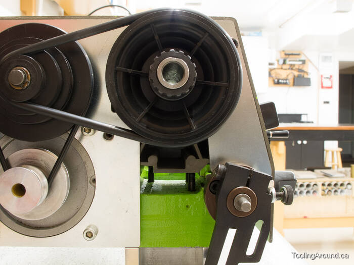
Gear Bracket (Skip to "Spindle Gear and Belt".)
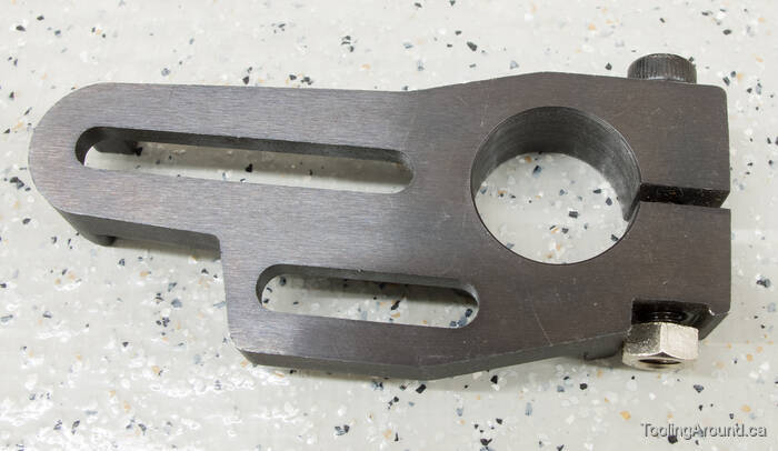
The gear bracket is made of steel. The upper slot is for the bearing that carries the Z1-Z2 gear pair and the lower slot is for the reversing gear (described, below). The SHCS is tightened to pinch the end of the bracket snugly on the bearing block.
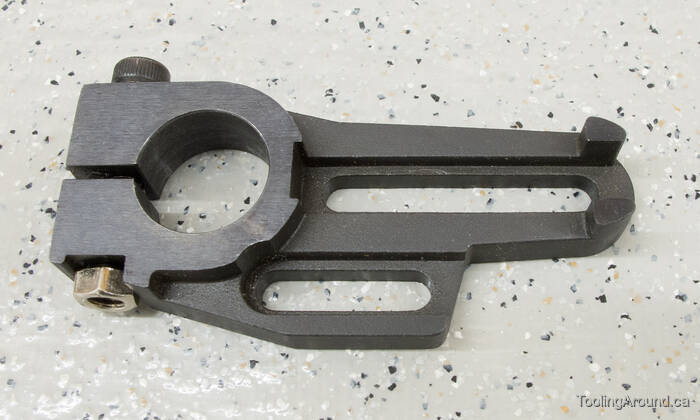
On the back side, the slot will hold fixing nuts so they won't turn while their screws are being tightened.
Spindle Gear and Belt (Skip to "Intermediate Gear Pairs".)
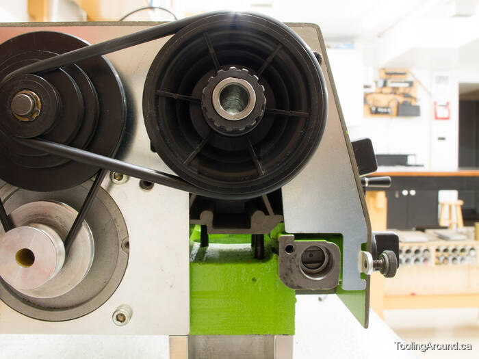
This is the 15-tooth gear that fits on the lathe spindle. The grub screw is toward the left side (outboard end) and is tightened against the flat on the end of the spindle.
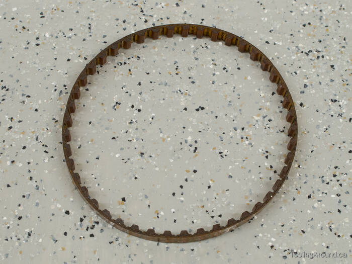
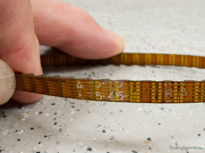
The “cogged belt” described in the manual is a T5-45 toothed belt. It is 5 mm wide and has 45 teeth, for a total length of 225 mm. The pitch is 5 mm and the tooth height is 1.2 mm. It's made of polyurethane, with 5 reinforcing threads running along its circumference.
Intermediate Gear Pairs (Skip to "Left-Hand Thread Cutting".)
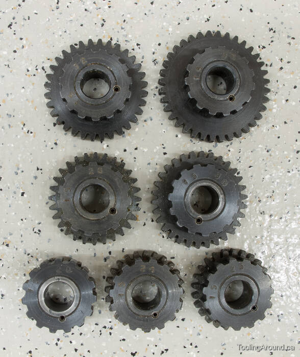
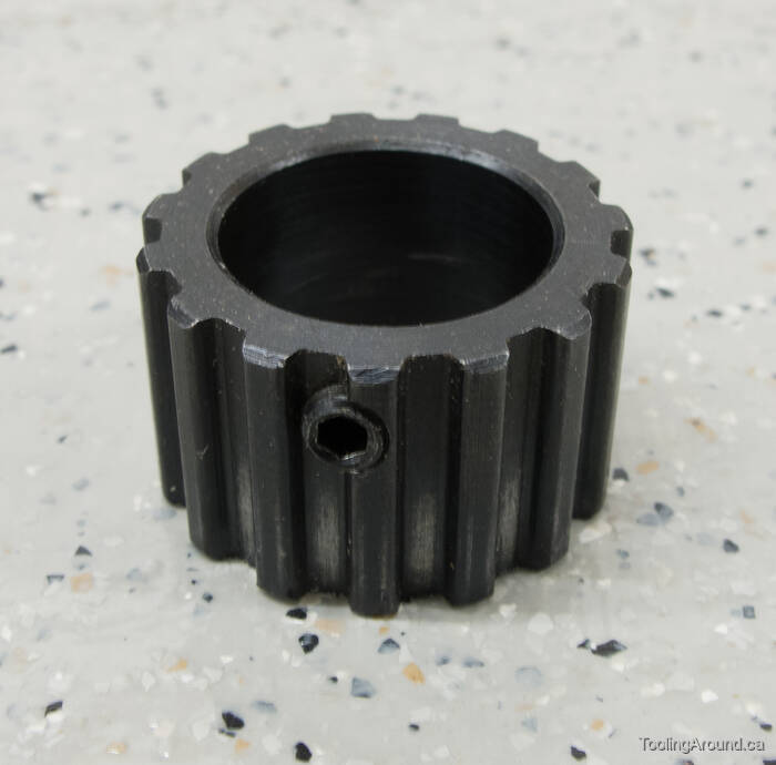
Here's the family portrait of the set of Z1-Z2 gears that come with the No. 3413 attachment.
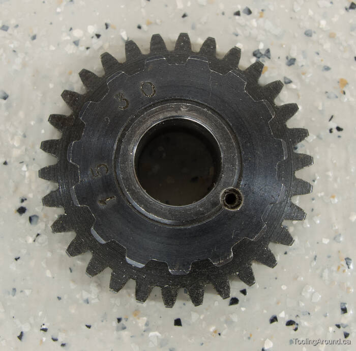
Each “gear” consists of two gears. The Z2 gear has a boss and the Z1 gear is pressed on to this boss. As you can see, a hole was then drilled through the joint and a roll pin was inserted to lock the two gears together.
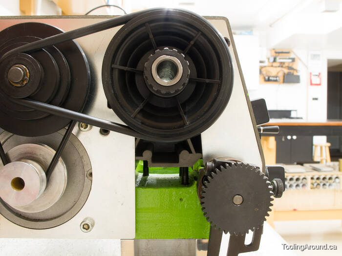
Left-Hand Thread Cutting (Skip to "The Assembly".)
To cut left-hand threads, another gear is introduced into the gear train. This gear reverses the direction of the gear that it drives and does not affect the gear ratio.
This is the reversing gear, which happens to have 17 teeth, although that's irrelevant other than making the gear a convenient size to fit in the limited available space. As you can see, the gear has its own bronze bearing and runs on a shoulder bolt that's used to fix it in the shorter slot in the gear bracket.
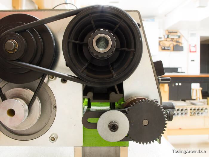
Assemble the gear with the thin washer between the gear and one of the nuts. Because the shoulder projects a tiny bit past the bearing, the washer will bear on the end of the should when the first nut is tightened (not too tight). With the first nut in place, the gear should turn freely on the bolt. After inserting the bolt through the gear bracket slot, fix it in place by using the other nut on the back side of the slot.
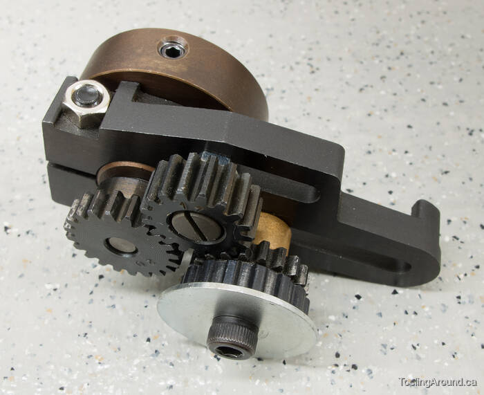
The reversing gear sits between the Z2 and L gears. The first nut spaces the gear away from the bracket, right where it needs to be.
Here you can see how both nuts are kept from turning in the slots.
The Assembly
Attach gear W to the spindle, with the grub screw toward the end of the spindle and fix it in place.
Attach the bearing block.
Hang the gear bracket on the bearing block. Don't bother to tighten its SHCS.
Fix the L gear on the shaft.
Assemble a Z1-Z2 gear pair on the bracket and adjust it in the slot so the gears are fully engaged but spin freely with no binding. Tighten the SHCS and check again for proper engagement.
Install the belt and tighten the SHCS that holds the gear bracket to the bearing block, making sure that the belt tension is snug but not tight.

Here's a drawing of the Toyo thread cutting attachment.
If you decide to make your own attachment, don't feel that you need to make a replica of the one from Toyo. I suggest that you start by finding a source for the required gears. They should be an appropriate size if you use 0.9 MOD spur gears. After that, use your own imagination to figure out how to hold them in the correct relationship to work on your lathe.