 Tooling Around
Taig Lathe – Tailstock Die Holder
The die holder itself slides on an arbor that is attached to the tailstock ram. This arrangement keeps the die true to the workpiece, which is held in the chuck, ensuring that it starts its cut accurately.
This die holder is based on Neil Butterfield's design. (His site seems to have gone walkabout. If you know where it it is, please let me know via the Contact link at the bottom of this page.)
Arbor (Skip to "Die Holder".)
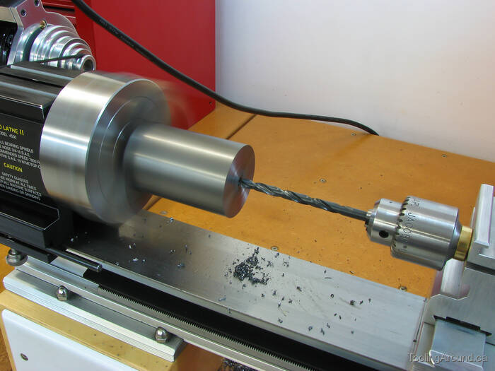
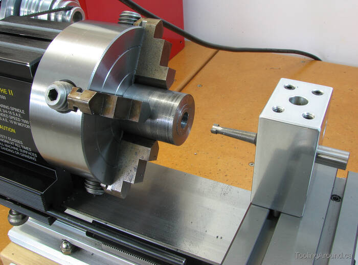
This is the first step in making the tailstock arbor. Most of my projects start here. This will be the arbor on which the die holder slides.
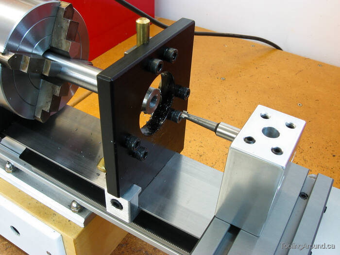
This is how I held the arbor to drill it lengthwise using the Taig tailstock drill chuck.
I drilled a hole in each end of the arbor. One was in preparation for cutting a thread so the arbor could be mounted on the tailstock ram. The other was to provide clearance for a workpiece as its threaded portion passed through the die.
When I got to larger drill bit diameters, the lathe showed its limitations, so I moved to my drill press to complete the drilling.
It's important to face the end of the arbor so it will seat nicely on the tailstock ram, with the other end on the spindle axis of rotation.
Here, I'm boring the tailstock end of the arbor before cutting the threads. I was fussy because I wanted the arbor to fit to the tailstock ram as accurately as I could manage.
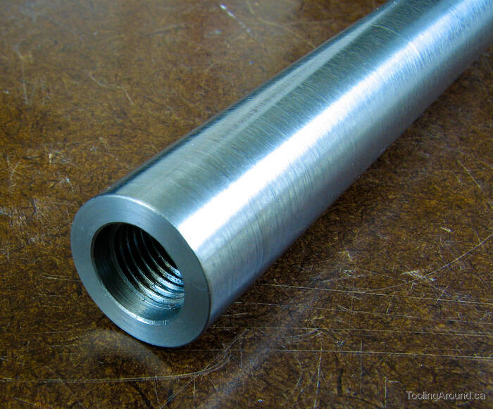
This is the tailstock end, showing relief for the non-threaded part of the tailstock ram.
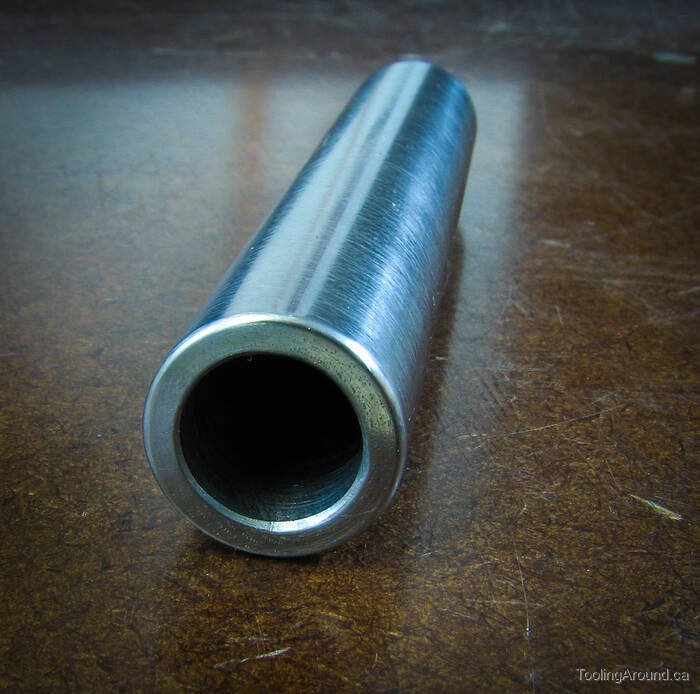
This is the end that faces the headstock, drilled to provide space for a part being threaded.
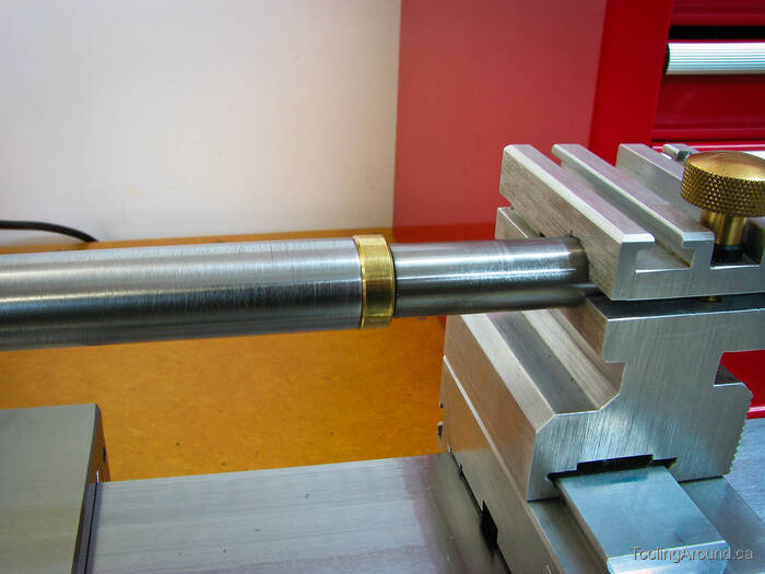
This is how the arbor's attached to the tailstock ram.
Die Holder (Skip to "Boring A Recess".)
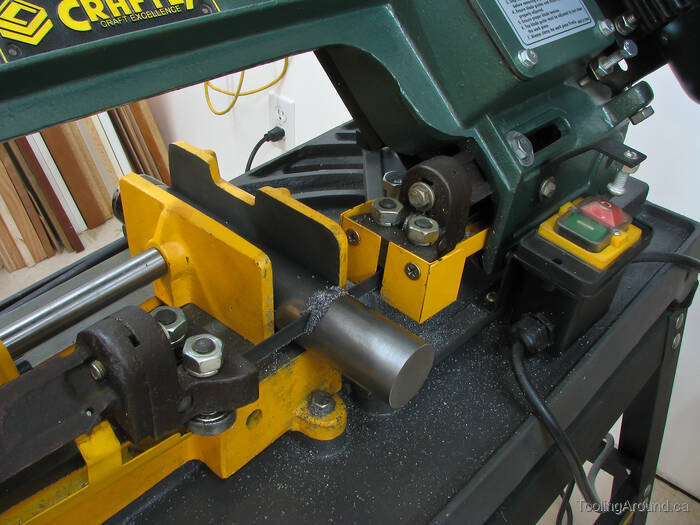
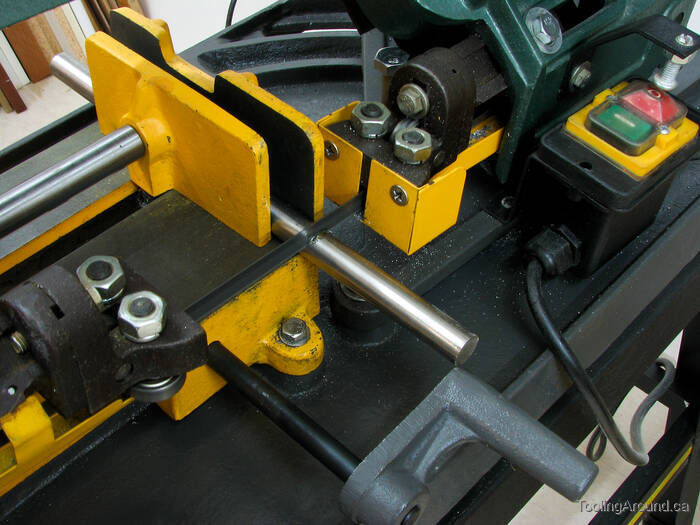
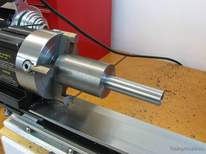
The next part to make is the die holder, which will slide on the arbor. So, back to the bandsaw with a length of 1.5″ 12L14 steel bar.
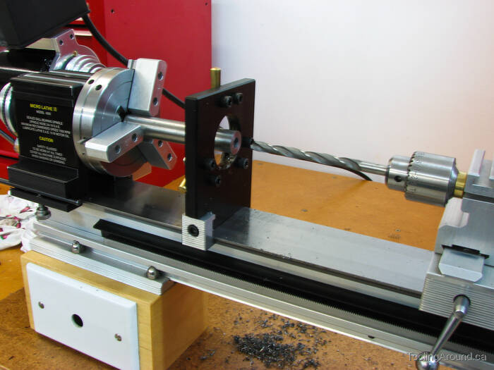
After facing the end of the bar, I used a centre drill and then progressively larger drill bits.
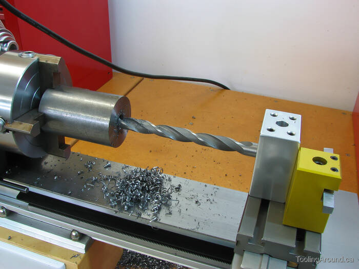
When I wanted to use a drill bit larger than the Taig-supplied 1/4″ chuck could hold, I used my boring tool holder. As described elsewhere on this site, the boring tool holder was initially prone to twisting. That's why the second toolpost is being used to hold it in place, pending correction of the problem (by adding alignment pins to the bottom of the boring tool holder).
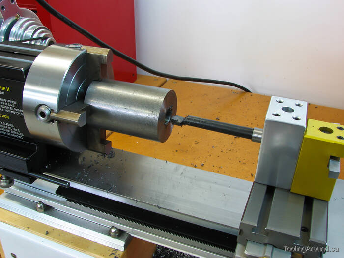
Boring for a sliding fit on the tailstock piece. One should use the shortest boring tool that will make the cut, so as to minimize flexing of the tool. In this case, this is the shortest suitable length.
A test fit showed that the arbor is a nice, sliding fit in the die holder.
Boring A Recess (Skip to "Adapter".)
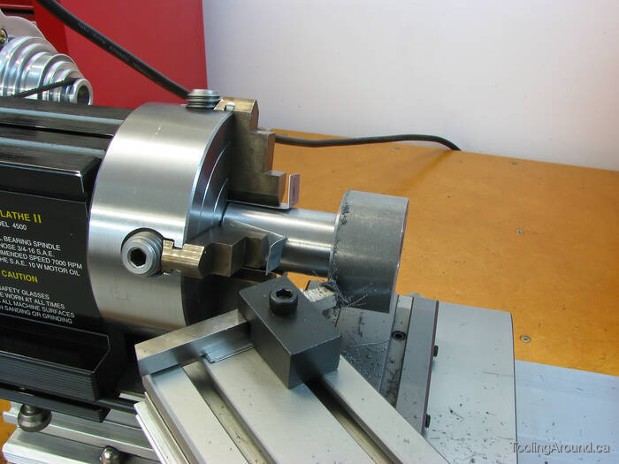
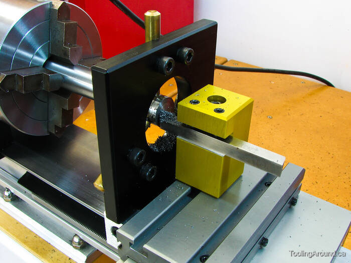
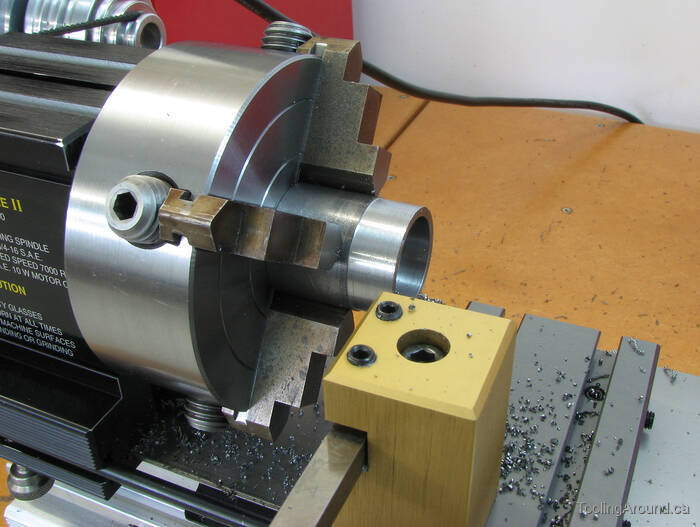
After reducing the diameter of much of the die holder and reversing it in the chuck, I cut a chamfer. As you can tell from the photo, this required care, to avoid the whirling jaws of the chuck.
A light cut was all that was required to clean up the die holder.
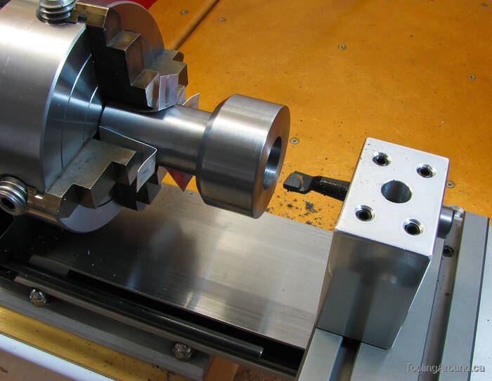
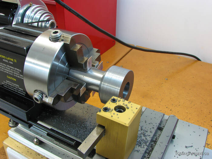
The next step was to enlarge the bore, making a recess just deep enough for a sliding fit for a 1″ diameter die. Note the use of a much shorter boring bar than was used, previously.
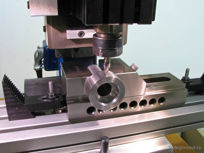
Holes were drilled at 180° from each other, to accept grub screws to hold a die.
I also drilled and tapped a hole at 90° from one of these, to attach a handle.
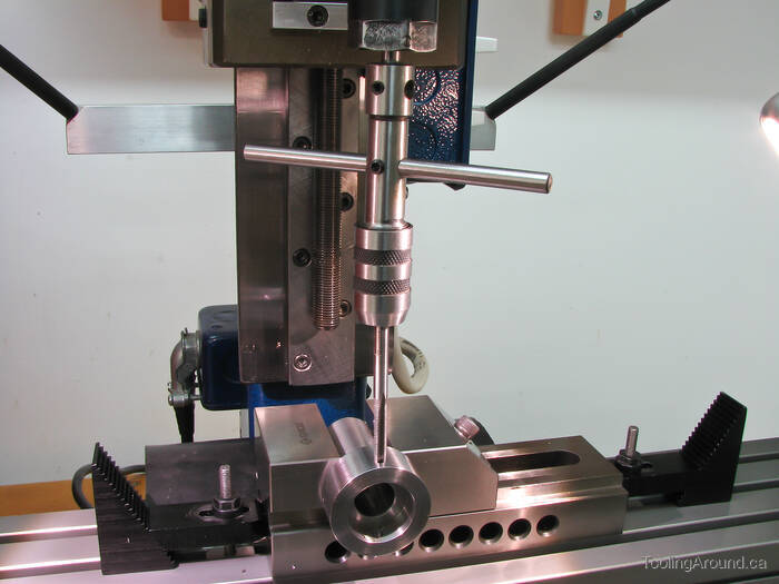
Both holes were threaded 10-32 for grub screws. I turned a taper on the end of each grub screw to match the holes provided on dies.
If you make something like this, take care to position these holes accurately. They must be the correct distance from the bottom of the recess, so the grub screws will not draw the die up from a firm seat on the bottom of the recess as they're tightened.
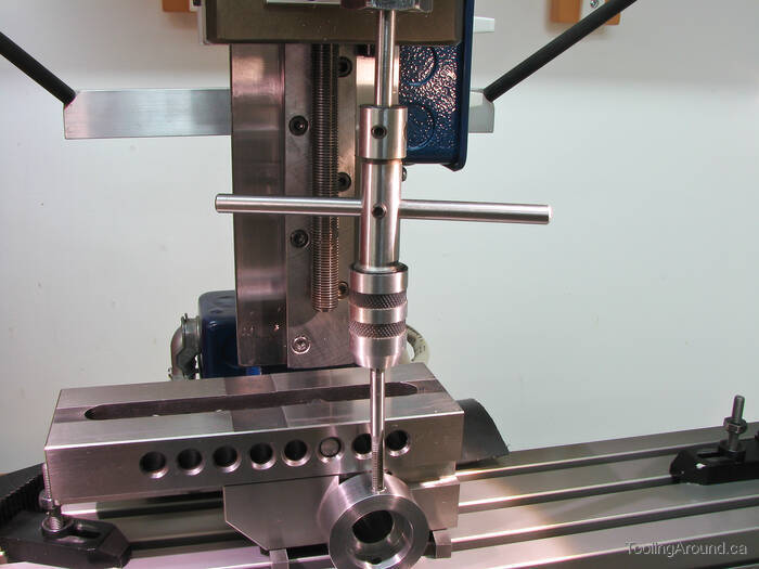
Note that the vise is upside down and is sitting on two lathe tool blanks to keep it clear of the table. They're required because the die holder would otherwise contact the table. But that's not the interesting part. The reason for turning the vise over is that this ensures that the hole being tapped is exactly 180° from its mate on the other side of the die holder. This is more accurate than repositioning the die holder in the vise. The same principle can be applied from time to time for other machining operations and can be summed up as taking advantage of the inherent accuracy of tooling.
To be honest, I don't remember if I set this photo up “after the fact” or if I was just setting it up or tearing it down at the time. Regardless, I've included it because it illustrates a principle. The reason for my doubt is that the vise is not held to the table.
Adapter
Dies are not all the same diameter. The recess in the die holder is for dies that have a 1″ diameter. I made an adapter for 13/16″ dies. It's important to achieve a very close fit to reduce runout to an absolute minimum.
Next, I turned the adapter to the correct diameter, a very close fit to the die holder. Then I drilled two holes at 180° to each other, to let the tips of the grub screws pass. Finally, I used a cutoff tool to part the adapter from the rest of the bar.
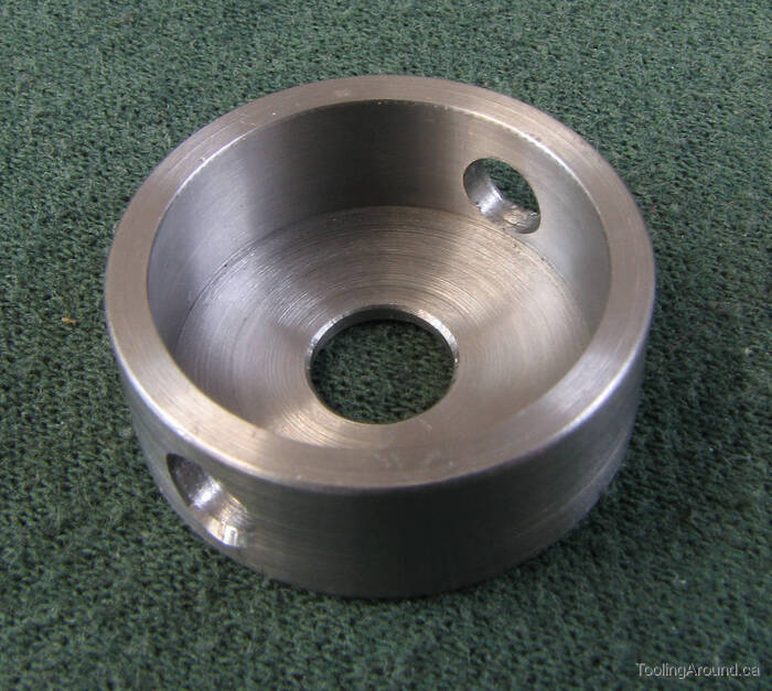
Here's the result. The thickness of the base is precise, to ensure proper seating of the smaller dies when the grub screws are tightened.
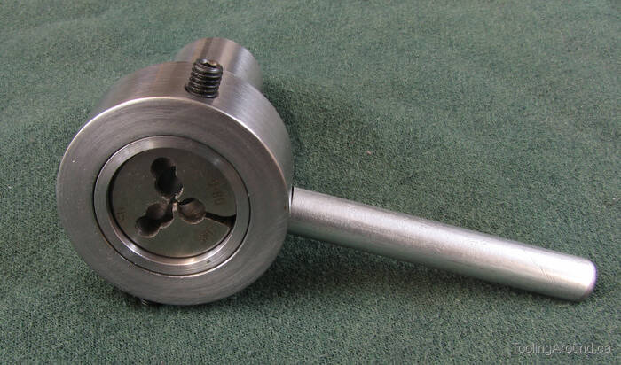
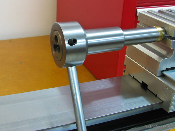
Here's the finished accessory, complete with a die. In use, the handle rests on the edge of the lathe bed, where it's free to move longitudinally, but keeps the die holder from turning as threads are being cut.