 Tooling Around
Dining Room Lamps
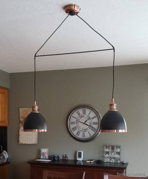
It was time to replace the lamp that hung above our dining room table. The challenge was to find one that suited our taste and our budget. My wife had three nice pendant lamps above her sewing table and we eventually decided that we liked them enough to use two more above our dining table.
As often happens, a simple project threatened to spiral out of control. Two lamps meant that we needed two electrical boxes, one each side of the one that was already there. The existing one would have to be removed. However, our house is a bungalow, so any change above the ceiling meant that I would be dealing with a thick layer of attic insulation and the vapour barrier under the ceiling joists. As a final challenge, the ceiling has a textured finish and I had absolutely no confidence that the necessary patch over the hole where the existing electrical box is fitted would match the rest of the ceiling.
Spreader (Skip to "Ceiling Plate".)
The first job was to make a spreader that would hold the lamps an appropriate distance apart.
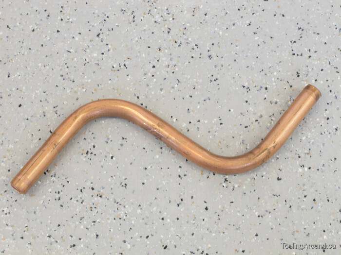
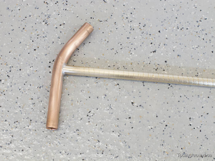
I have no idea where this bit of 1/4″ copper tube had come from before landing in my scrap box, but it looks just about right.
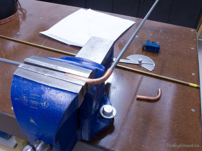
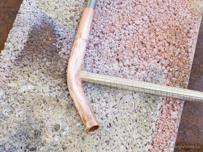
The first job was to reduce the 90° bends to something more suitable. I inserted the ends of some 1/4″ bar stock in each end. This kept the end in the vice from collapsing and gave me something to pull on at the other end.
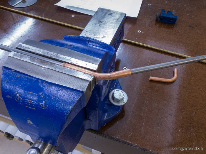
That looks about right.
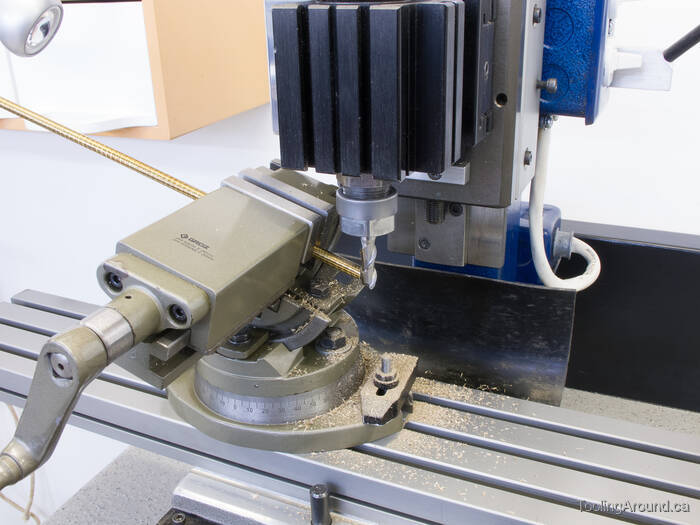
The spreader bar is made of 1/4″ brazing rod, just because I had a fair bit of it on hand. Off to the mill to carve out a seat for the copper tube.
That looks about right. I drew a line on the bar at each end, so I could align the cuts close enough to matching angles. I just made sure the line was facing up when closing the vise on it on the mill.
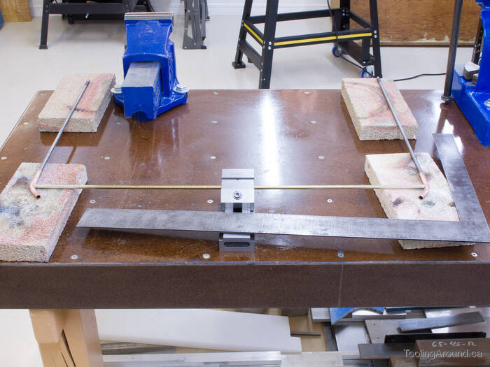
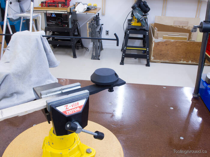
Here's the setup for soldering the tubes to the ends of the bar. A length of 1/4″ bar in each tube ensured that those ends of the tubes were on the same plane. The vice held the spreader bar still during soldering. The carpenter's square ensured that the tubes were at 90° to the spreader bar, so the power cords would be directed straight down when the lamps were hung.
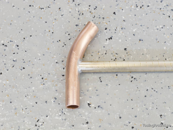
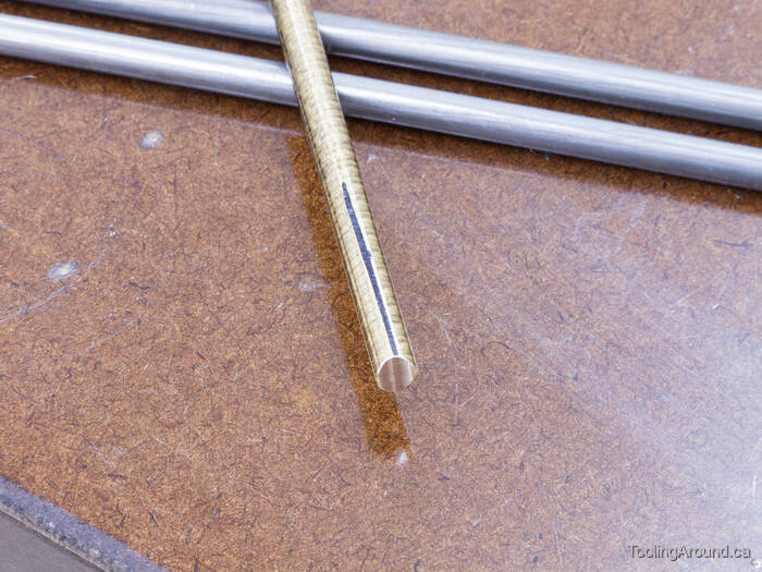
Some flux, a bit of solder and then the tubes were trimmed to the desired length.
There's the spreader, hanging around while the primer paint dries.
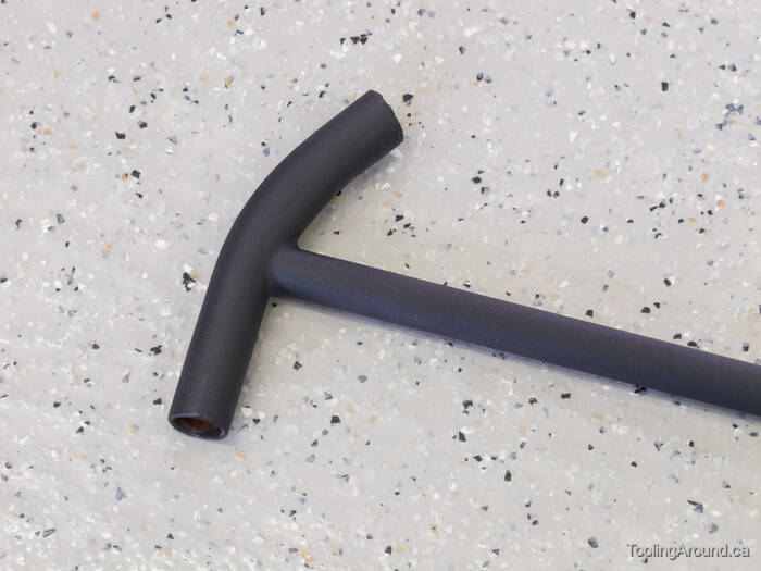
With a finish coat of paint, the joints looked pretty good.
Ceiling Plate (Skip to "Boss".)
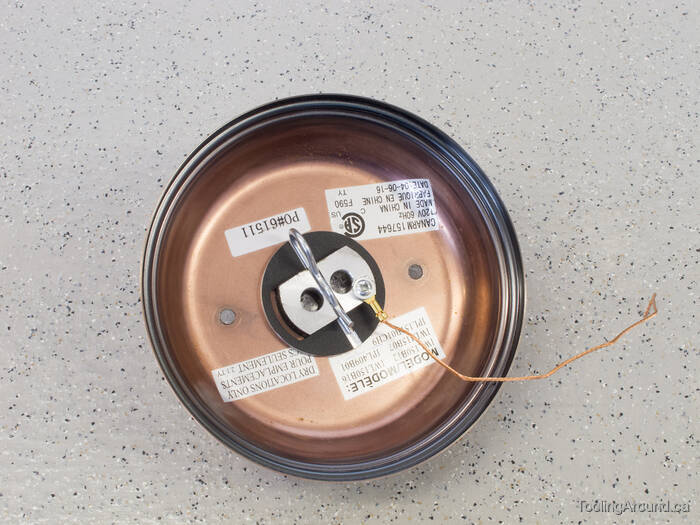
Since the power cords would converge at the electrical box, I needed a way to hold them there safely. As supplied, each lamp had a ceiling plate with a plastic-lined metal bushing to pass the cord through to the electrical box. The cord was tied in a knot inside the ceiling plate and the knot was held firmly together with a small cable tie. My objective was to replicate this for a pair of cords, with one added feature: the whole assembly needed to be able to be turned after it was hanging above the table, so the lamps would be aligned with the table.
It made sense to make a boss to hold the power cords, with the boss able to rotate in a larger hole in the ceiling plate. So, start by using a hole saw to make the larger hole.
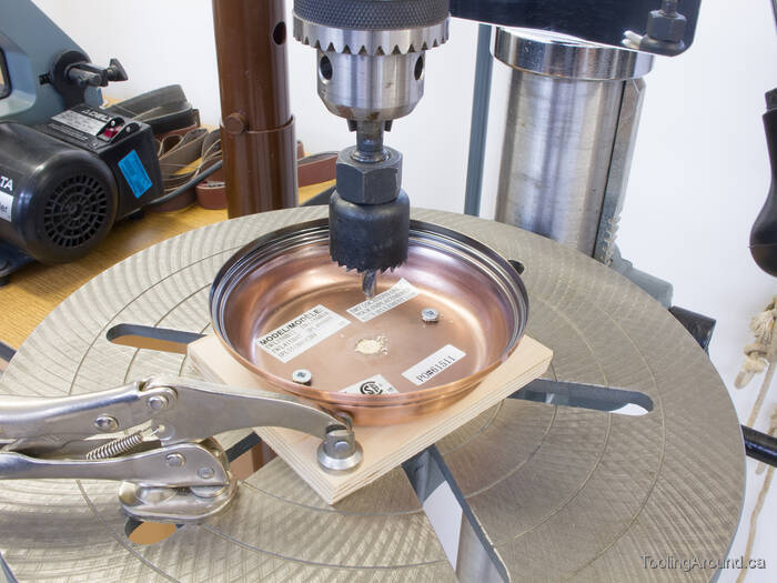
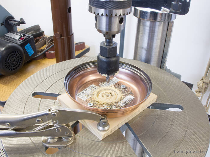
The screws through the mounting holes and into the plywood worked very well to secure the ceiling plate for hole cutting. The operation was completed with no damage to the finish on the ceiling plate.
For the next operation, I needed a wider slot in a tool post. Good thing they're inexpensive.
After trimming the corners of the plywood, I was able to mount the ceiling plate on a faceplate and bore the new hole to a smooth finish and the desired diameter.
As you can see, this operation necessitated use of riser blocks for the headstock and the toolpost. That's why I had to modify the toolpost to hold the boring bar, as the boring tool holder that I would ordinarily use is not compatible with the riser block.
Now that I had the larger hole in the ceiling plate, I knew the required diameter for the part of the boss that would have to fit in that hole.
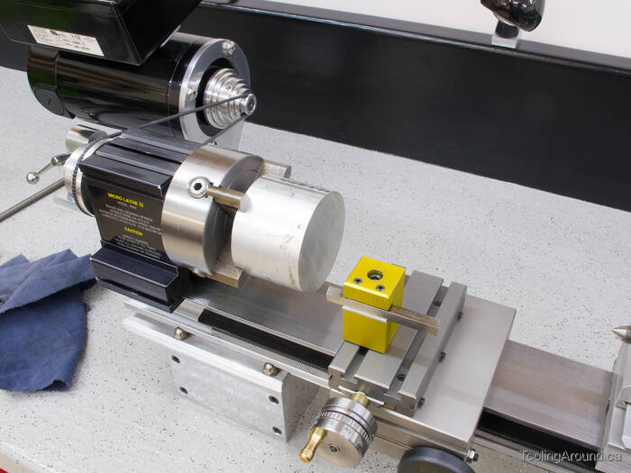
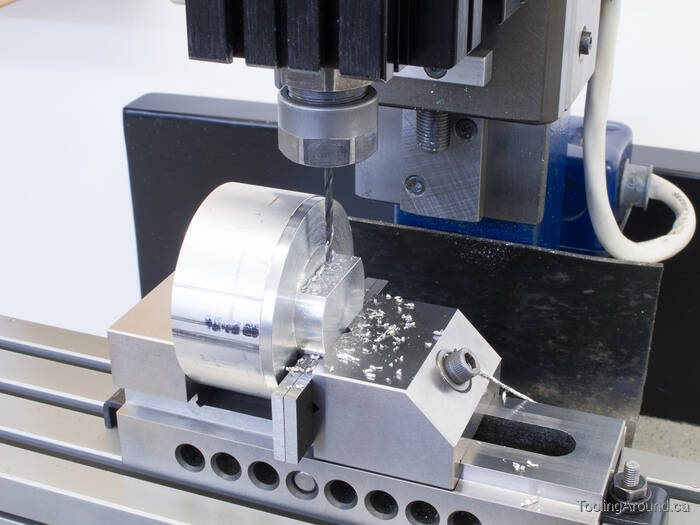
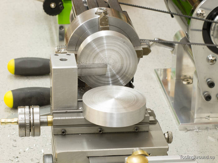
I had a (very) short length of a large aluminum bar on hand, 2-1/2″ diameter, if I remember correctly. This was much larger than I needed, but I had no other stock that was large enough. So, off to the lathe to make a facing cut and turn a short stub that would be a close fit to the new hole in the ceiling plate.
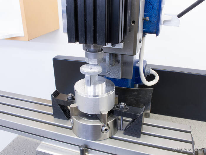
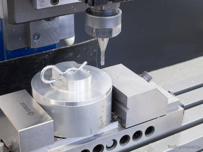
On the mill, I centred the workpiece by indicating off the stub.
You'll notice that a short length of the larger diameter has had a light cut. That's because later, the boss will be reversed in the chuck and I'll need a true surface to centre the boss for further turning.
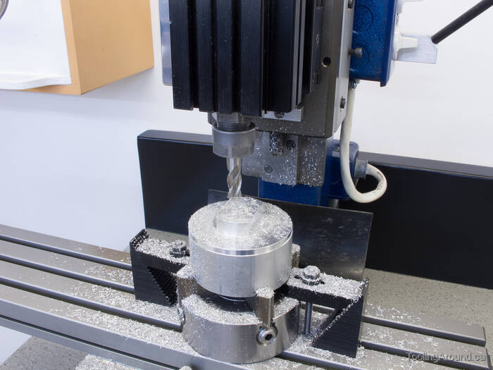
The stub was milled on each side in preparation for a retaining ring.
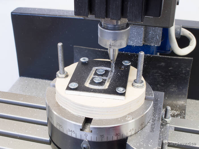
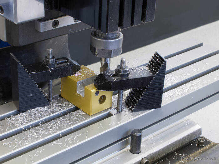
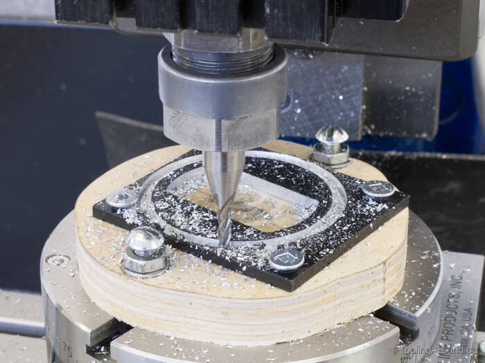
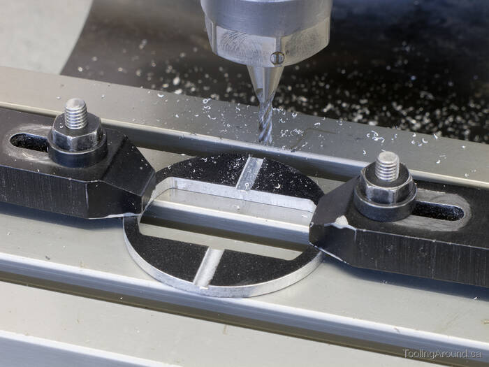
Now that the size and shape of the stub were established, I could cut the appropriate hole in a scrap of 1/8″ aluminum plate. The two screws in the middle are to hold the scrap piece after milling.
The cut was made by “ramping down”—lowering the milling head while advancing the table. After reaching the desired depth of cut, the cut was completed and the ramping down process repeated until the cut was all the way through.
Using the same ramping down technique, the retaining ring was completed.
It looked great, except for a rookie mistake measuring the slot. It's too long. Functionally, however, it's just fine, so I swallowed my pride and didn't make a new one.
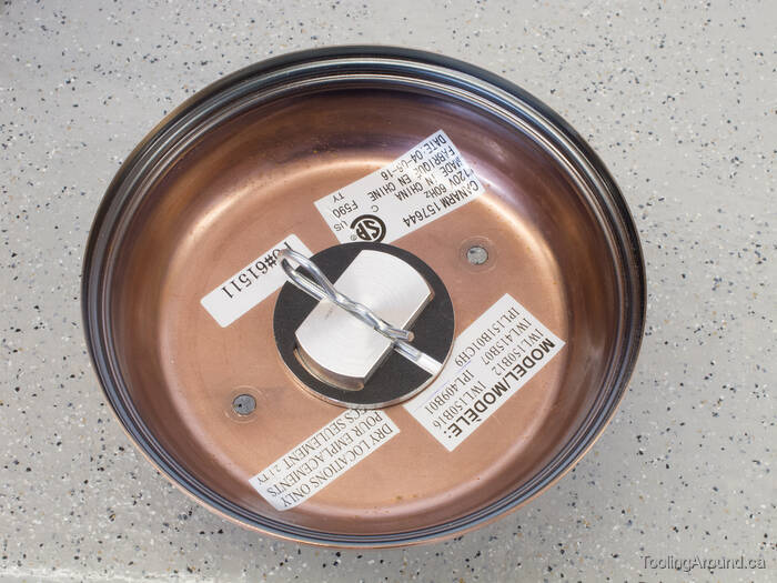
Here's how it looks, in the ceiling plate.
Drilling a hole for a clevis pin clip. The parallels ensure that the hole is at 90°. They were removed before the hole broke through the other side, of course.
Here's the clevis pin clip, with a groove milled across the top of the stub, so the clip won't be stressed too far open.
By the way, you can see that the stub sides were not milled right down to the main body of the boss. The little circular bit that's left helps centre the boss more positively in the hole in the ceiling plate.
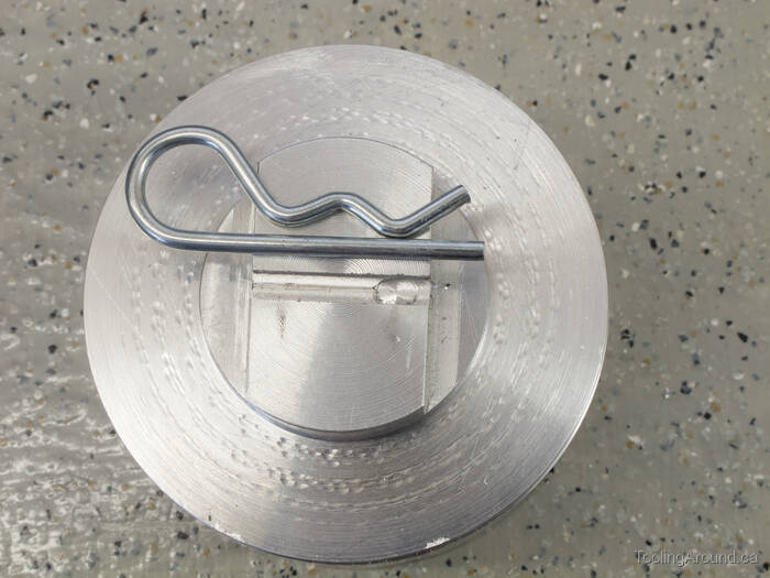
I milled a short “dimple” in the slot, so the clip can press into the dimple to help make sure that it won't slide out. I know: this is overkill, but it's also easy to do.
The clip wouldn't quite slide over the retaining washer, so it was treated to a groove of its own.
Finally, there's the boss, installed in the ceiling plate. As you can see, the weight of the lamps will be borne by the clevis pin clip and retaining washer. They're stronger than the screws that hold the ceiling plate to the electrical box, so they'll be fine.
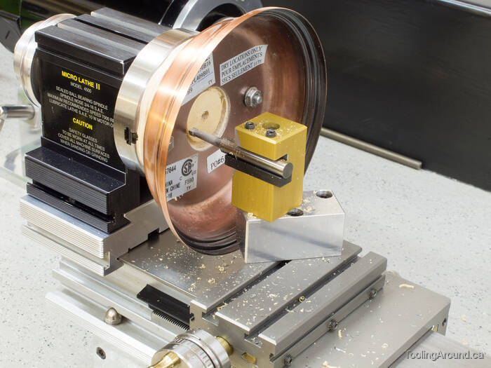
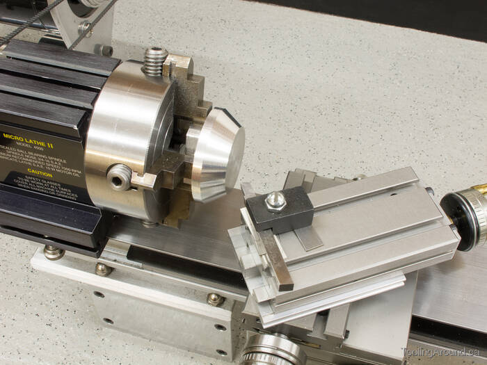
Okay, it's time to finish the other side of the boss. Remember that little bit of the stock that was turned early in this process? In this photo, you can see how it's used to centre the boss in the four-jaw chuck.
The stock is just a bit too big to clear the cross slide, so I had to hang a cutter over the edge of the cross slide and, bit by bit, reduce the diameter.
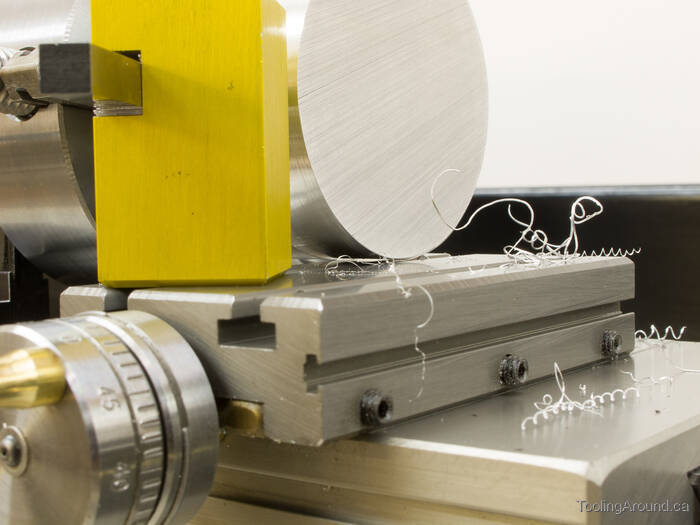
Here's how close it was.
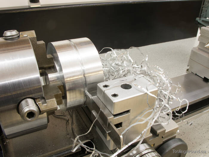
I used a parting tool to start the cut, intending to finish with a hacksaw, since a facing cut would make the end pretty, anyway.
The cut went well and I kept extending the cutoff blade. To my surprise, I was able to cut the entire rather large aluminum bar.
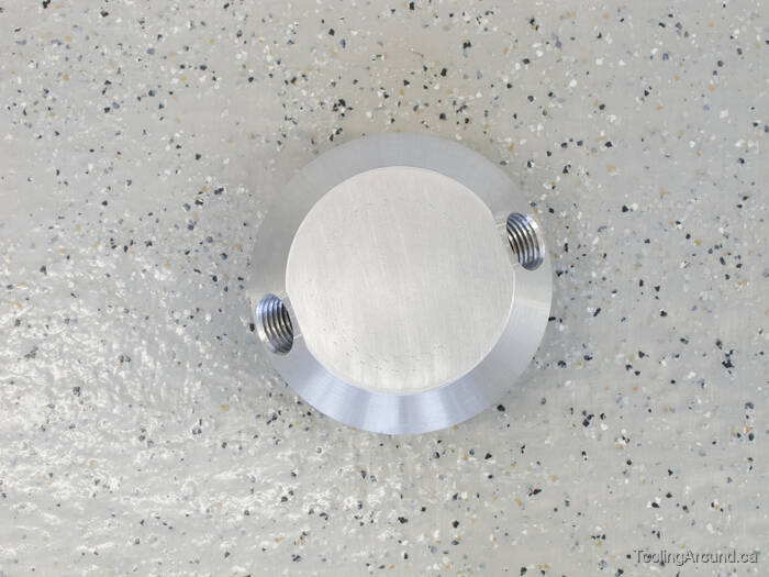
After facing the end, I turned a taper wide enough to seat the bushings for the power cords.
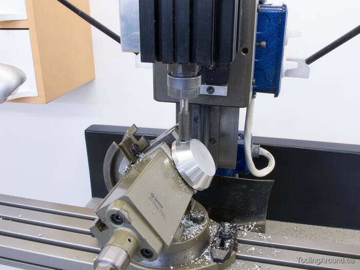
The it was back to the mill to drill holes for the power cord bushings. While the part was in the mill, I started the tap (M.10, if I remember correctly) so it would be true to the hole.
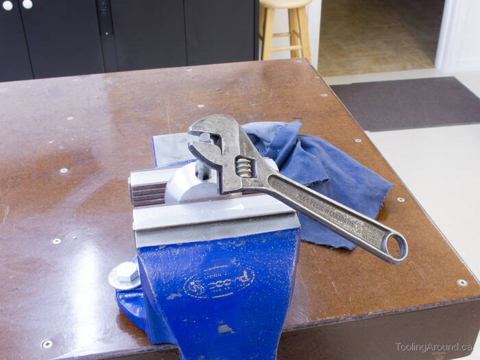
Then it was off to a vise to finish the tapping.
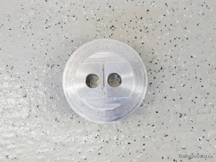
You can see how the cords will come through the holes, either side of the clevis pin clip, and into the ceiling plate.
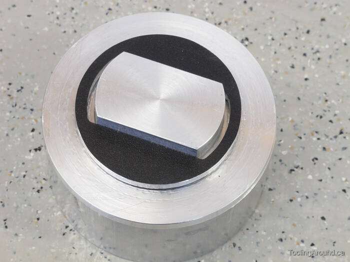
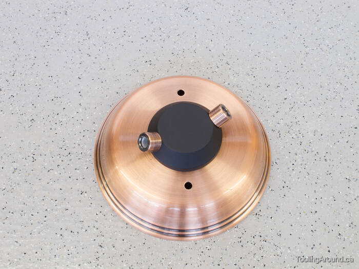
Here's the side that will be visible.
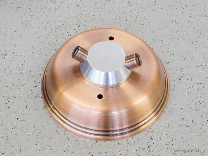
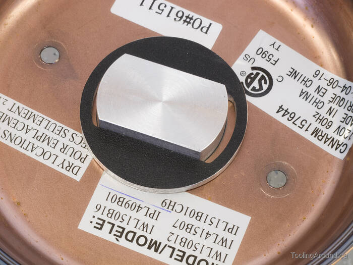
The first test fit.
Making sure that it hangs as intended.
Finally, a touch of flat black paint and it's finished.
Finished
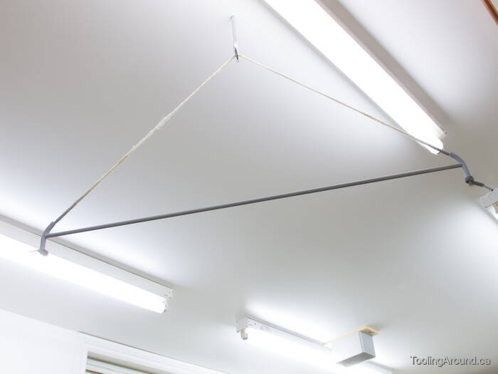
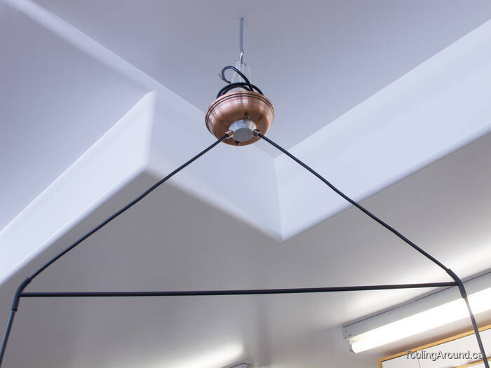
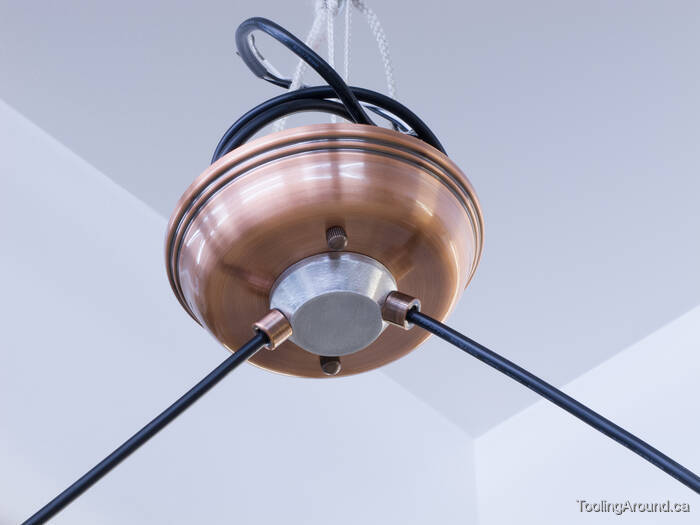
And it's ready for installation.
The project went well and we're pleased with the result. After hanging the lamps, it was easy to turn the boss to align the lamps with the table.
The only thing I would like to have done differently (other than get the hole in the retaining washer the right length) was to have used a more durable paint. This is probably a case where powder coating would have worked well. However, it wasn't quite enough of an excuse to acquire the necessary equipment to do powder coating. I just touched up a couple of minor spots with a black marking pen and let it go at that!