 Tooling Around
Video Storage Cabinet
Over the years, my wife and I have accumulated a collection of DVD and Blu-ray recordings sufficient to merit their own storage space. We had an old cabinet that almost served the purpose, but it had too few shelves and the shelves were poorly spaced for the new use. Additionally, in the (deliberately) softer light of the room containing our TV set, titles were getting a bit harder to read each year that we aged.
So, the solution called for some reconstruction of the cabinet and the installation of shelf lighting.
Shelves (Skip to "Push Button Switch".)
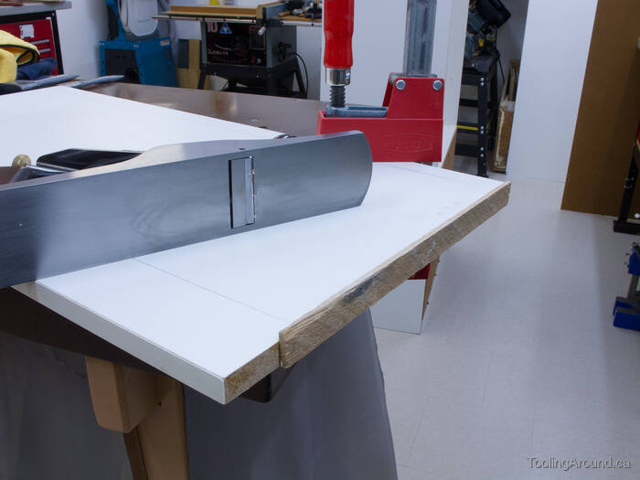
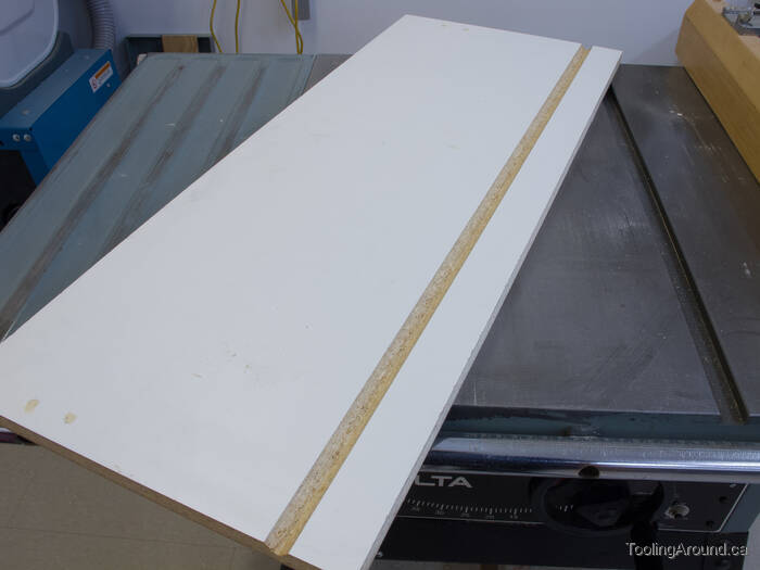
Originally, one of the shelves was adjustable and therefore a bit shorter than the shelves that were fixed in position. There was also a door, hinged on its bottom edge, that could be folded down until horizontal, so it could be used as a work surface. As a door was no longer required, it would be cut down and used as a shelf. All of the existing shelves were a bit wide and needed to be cut to an appropriate width.
This photograph shows the door, with a bit of hardwood glued to one end, to make it longer. Two pencil lines on the white surface show where the door will be cut to make it narrow enough to use as a shelf.
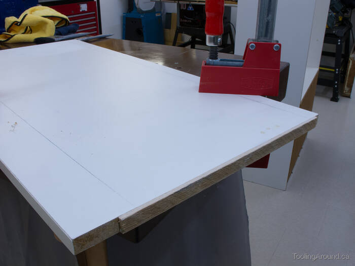
The hardwood has been planed flush with the door's surface, as is also the case for the adjustable shelf. Both of the modified shelves were cut to the length of the fixed shelves, on the table saw.
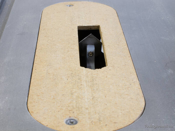
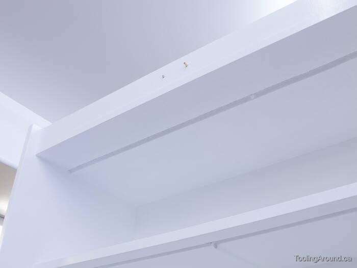
Also in the table saw, I installed moulding head cutters to cut V-shaped grooves on the underside of the shelves.
These grooves are the mounting locations for LED tape. Being hidden in the grooves, the tape will be out of sight and protected from damage, while also being perfectly positioned to shine light on the shelf contents.
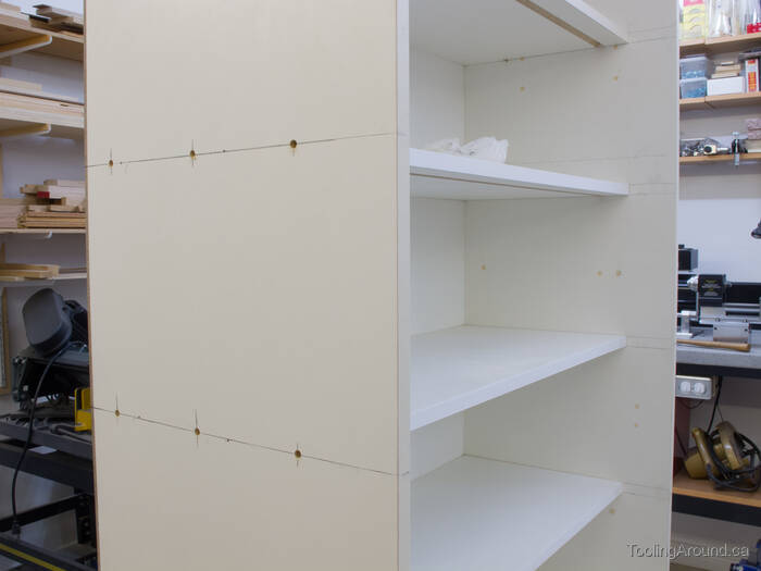
Next, the shelves were temporarily held in position by judicious use of my brad nailer. Then I drilled three 1/4″ holes through each gable and into the ends of the shelves. The back side of the shelves received the same treatment, the rear panel having been replaced by 1/4″ hardboard.
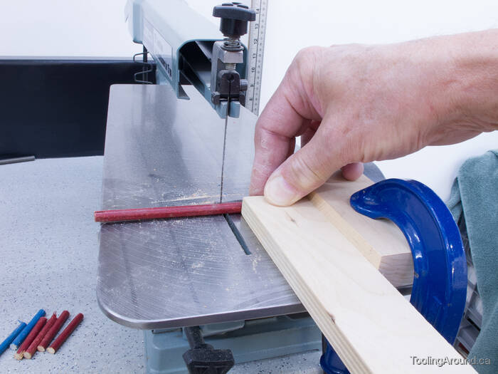
If you're of “a certain age”, you'll recognize the source of these dowels. This is how I cut them to length.
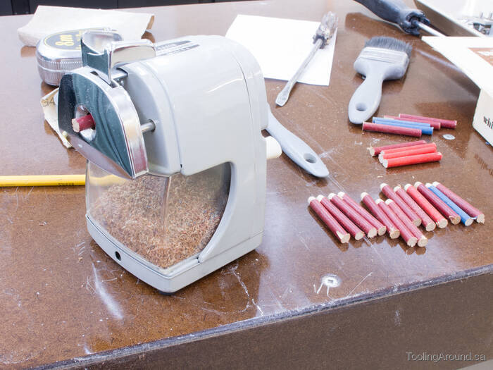
Next, the end of each dowel was chamfered in my high-tech dowel chamfering machine.
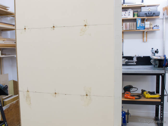
After receiving a wipe of glue, each dowel was driven into the holes, past the surface of the cabinet's gables. When the glue hardened, the holes were filled with wood filler to prepare them for painting.
Push Button Switch (Skip to "Conduit".)
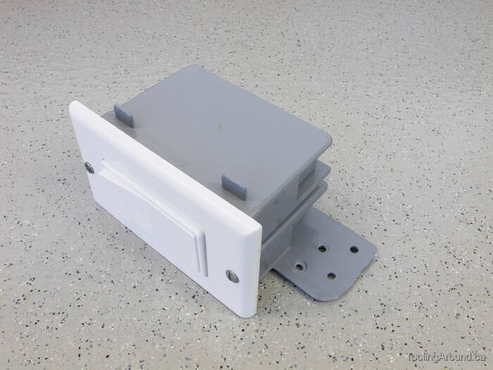
For a long time, I puzzled over a suitable mounting place for a light switch. Finally, it occurred to me that I could take advantage of the trim piece at the very top of the cabinet. So, I dug around in my box of electrical equipment and came up with the pieces to make this. I trimmed the decorative switch surround to make one edge flush with the bottom side of the plastic electrical box.
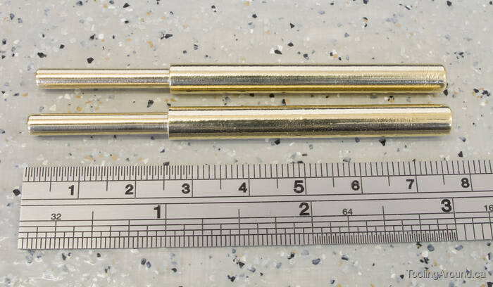
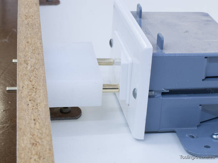
Next, it was off to the lathe to make a couple of pins.
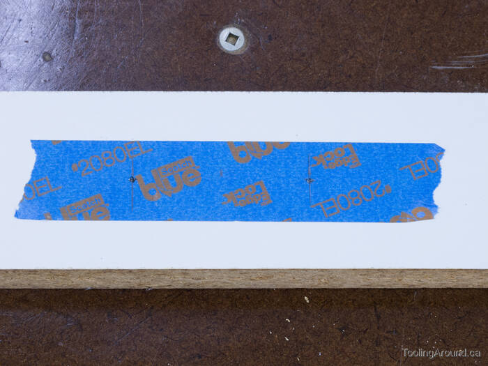
I used a bit of masking tape to protect the surface of the trim plate, where I used a brad-point drill to make two holes to clear the smaller end of the pins.
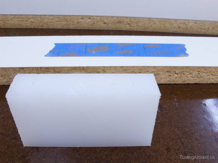
For the other side of the trim plate, I prepared a short length of UHMW polyethylene plastic, which would serve as a very slippery bearing block.
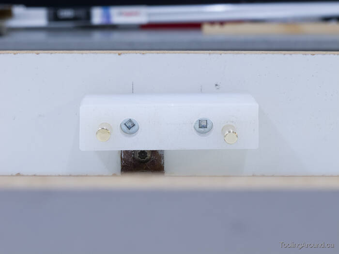
Here's the bearing block, fixed to the trim plate, with the pins in place.

A gentle push on the exposed ends of the pins switches from the “off” to the “on” position and back again.
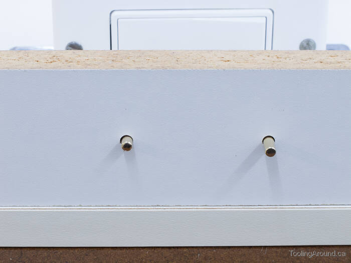
This is how it looks from the front. The cabinet's tall enough that the switch is not visible.
Pushing these pins is a strangely satisfying experience. The switch acts with a silky smooth motion and is almost completely silent. Add to that the durability of the switch and the ease and low expense of eventual replacement, and I'm very happy with the result.
Conduit (Skip to "Wiring".)
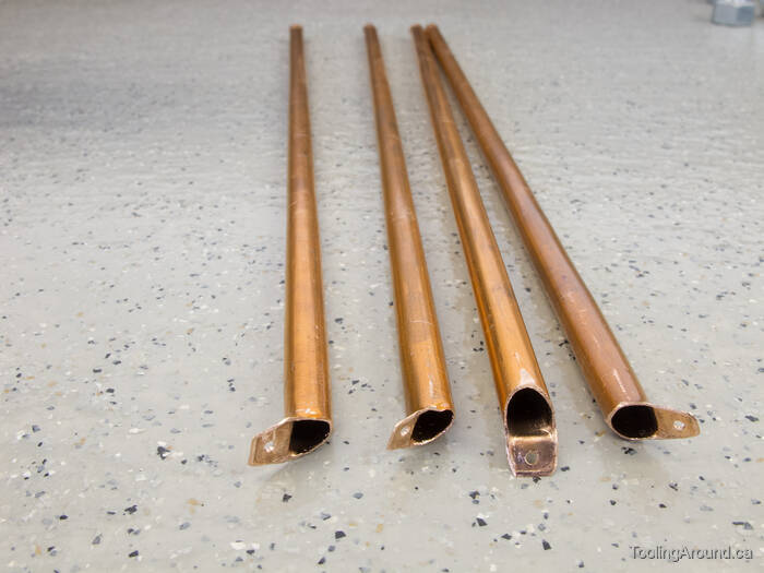
Wiring to the lights on the top shelf was no problem. It was a matter of drilling a hole and feeding the wire up through the top of the cabinet. The other four shelves, however, needed a different approach. I cut four lengths of 1/4″ copper tube and cut one end of each as shown in the photo.
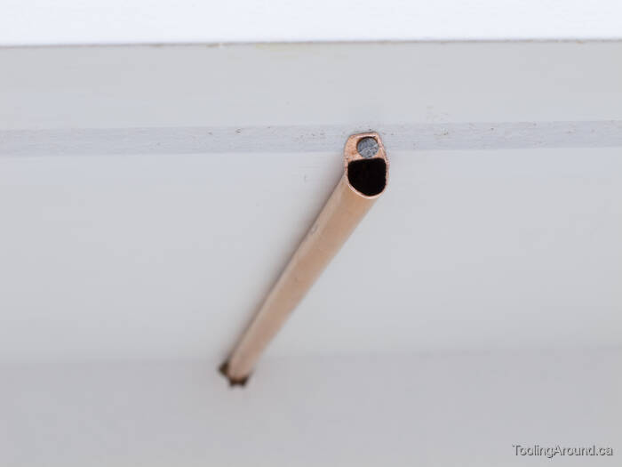
After passing one end through a hole in the back of the cabinet, I used a small nail through the tab to hold the other end next to the LED strip.
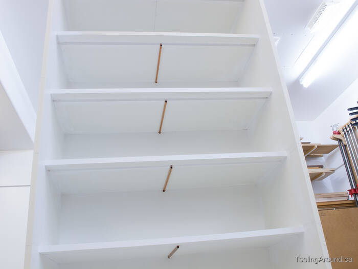
Here's the arrangement of the four lengths of “conduit”.
Wiring (Skip to "Finished".)
Careful as I was, I managed to pull the LED tape a tiny bit away from the groove. This may not have happened, had I used lighter wire, but 18 gauge was as light as I was prepared to use, to minimise voltage drop.
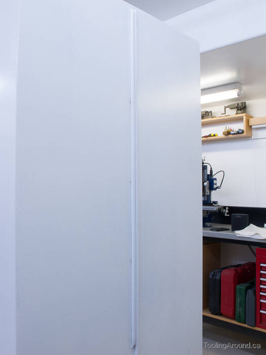
With the wiring in place, the gaps between the conduit and shelves could be filled with painter's caulk. After the cabinet was painted, the conduit was not particularly noticeable.
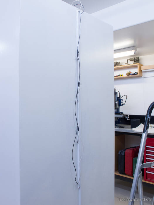
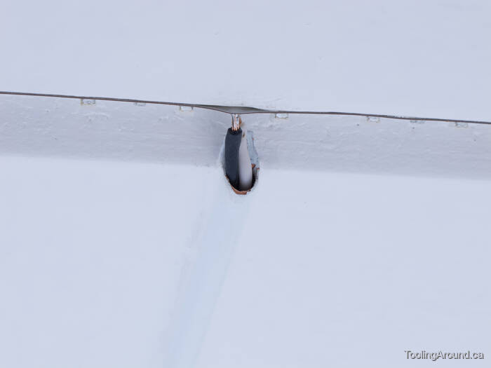
On the backside of the cabinet, a length of plastic wire cover was attached, with holes for the ends of the conduit. A second length of wire cover was installed next to the first, to cover the wire that led from the power supply to the mains socket.
Once the covers were snapped shut, the wiring on the back of the cabinet was hidden. I touched up the gaps with painter's caulk and the whole looked looked quite tidy. The reason for going to this trouble is that the cabinet was going to be placed where the back would be very visible. As it turned out, the cabinet is now against a wall and this work isn't visible at all.
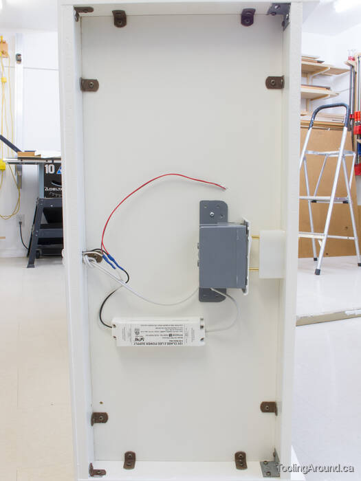
Here's the arrangement of the wiring, power supply and switch on the top of the cabinet. In this photo, the cabinet's on its side on a car mechanic's creeper, ready to be rolled out of the shop and off to its place near the television set.
Finished
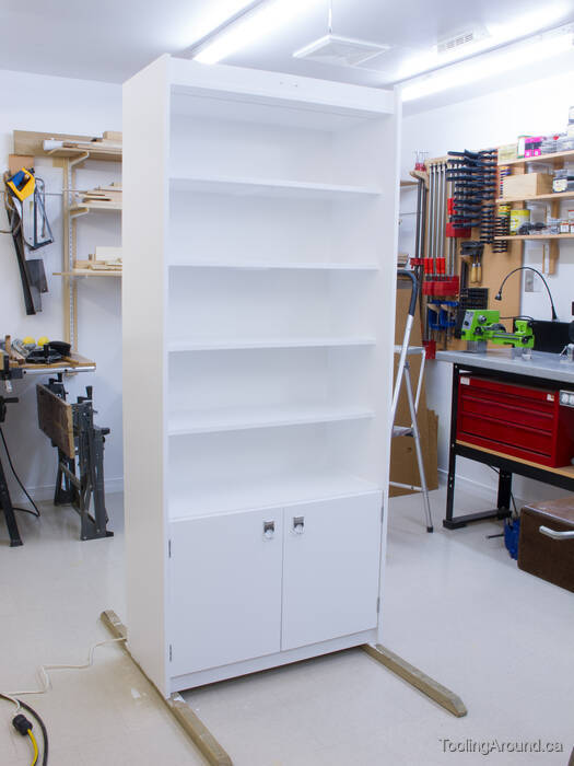
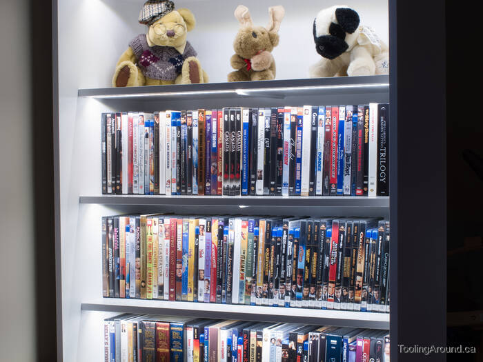
Here's the cabinet, lights off.
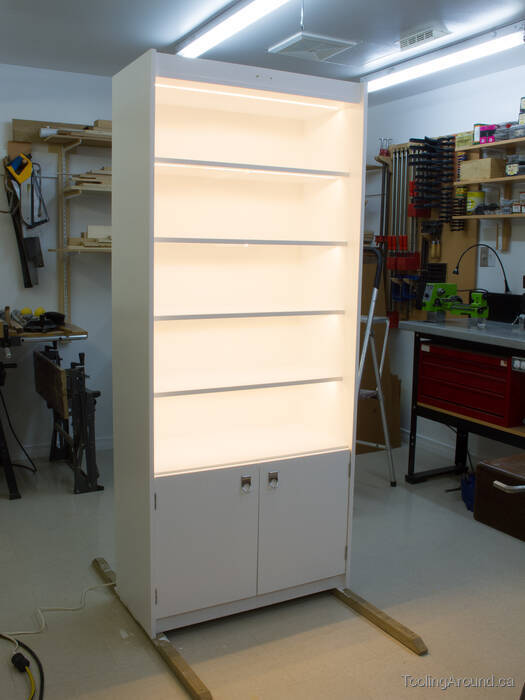
And here's how it looks with the lights turned on.
The LED tape was available with three choices of LED density: 30, 60 or 120 LEDs per metre. We weren't sure which to buy and opted for 120. As it turned out, it would have been better to use 60 LEDs per metre, as the light is very bright, indeed. On the other hand, we have no difficulty at all, reading the printing on the spines of the Blu-ray and DVD cases.