 Tooling Around
Taig Mill – Stamp Guide
This little project was the result of another one, where I needed to stamp some numbers in precise locations. While thinking about it, it occurred to me that the mill table is the obvious way to position a work piece, so all I needed to do was make a guide that I could put on the headstock.
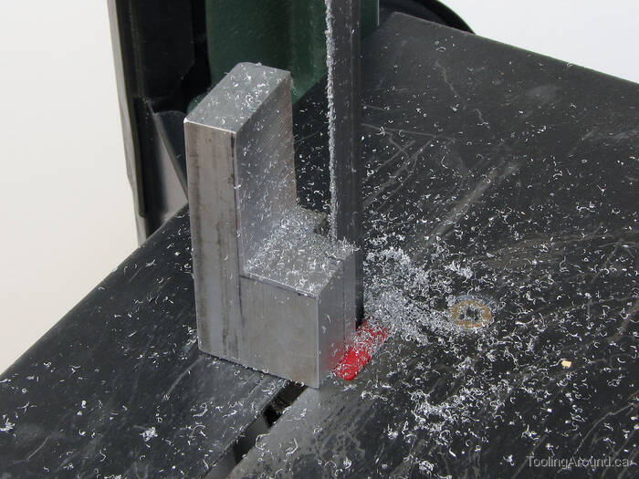
There was a suitable piece of aluminum in my pile of odds and ends, so the project started where most do: on the band saw.
Once roughed out, the work piece was ready for the mill.
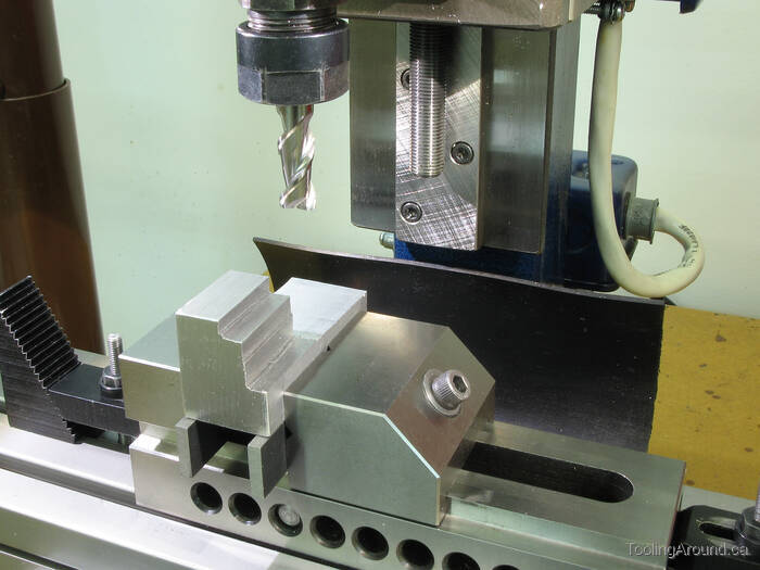
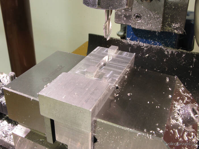
The work piece was held in this position for all of the milling on the front side.
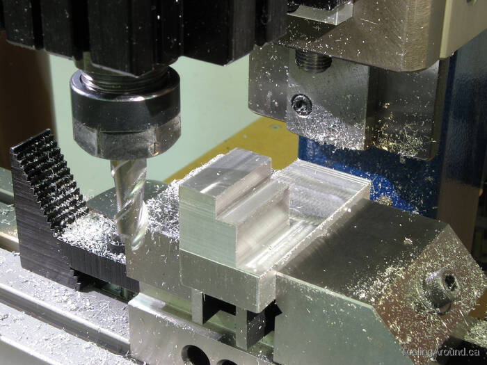
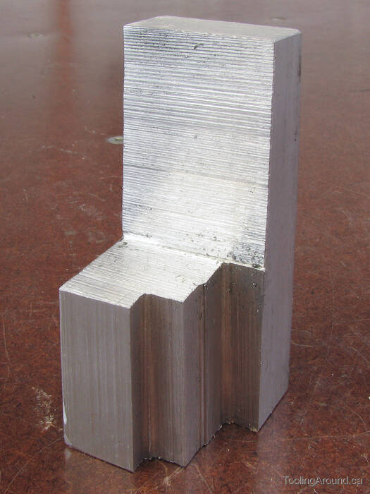
The front side is milled. As you can see, not all of the bottom edge (facing the camera) has been milled, yet, because the cutter is too short to reach that far.
The body started as a piece of mystery metal. It was clearly aluminum, but of unknown composition and was actually a bit “gummy” to machine, resulting in a generally rough finish. You can see how the long edge next to the vise jaw sort of curled over.
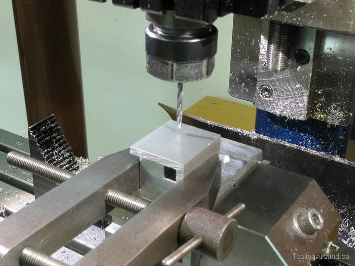
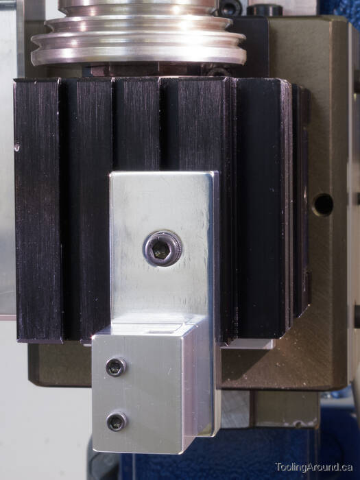
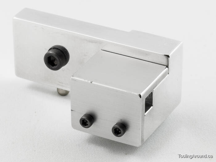
A short piece of 1″×1/8″ aluminum angle has been clamped to the body. It will serve as the cover that holds the stamp in position. Holes were drilled through it and into the body, preparatory to tapping for 4-40 socket head cap screws. This ensured that the holes in the cover matched those in the body.
The drill bit was reversed and gripped lightly in the collet so I could use it as a guide. The mill table was positioned so the end of the drill bit would pass easily through the hole, with no interference. Then a larger bit was used to enlarge the hole to a close fit for the 4-40 cap screws. Because the cover was positioned accurately for this hole, it was a simple matter to reposition the table to enlarge the other hole (because they are 0.5″ apart).
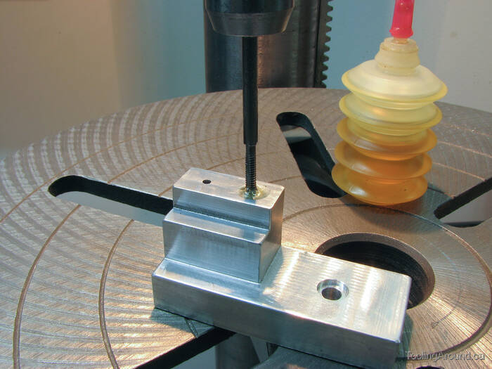
A 4-40 tap was held in a tap handle, the other end of which was held loosely in the drill press chuck. This ensured that it was held in a vertical position.
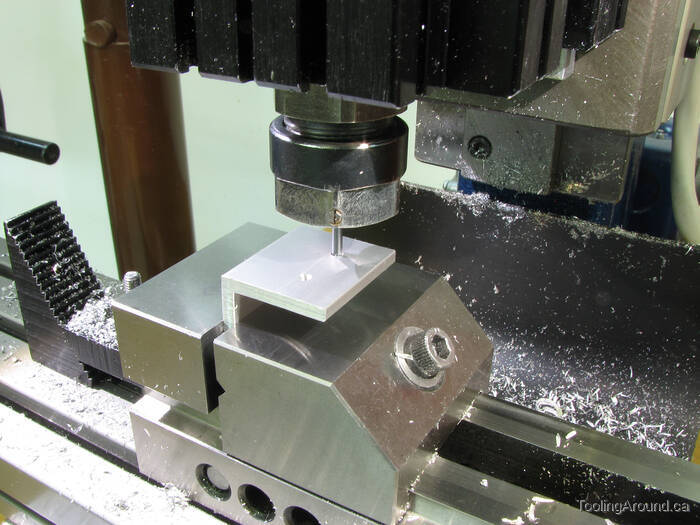
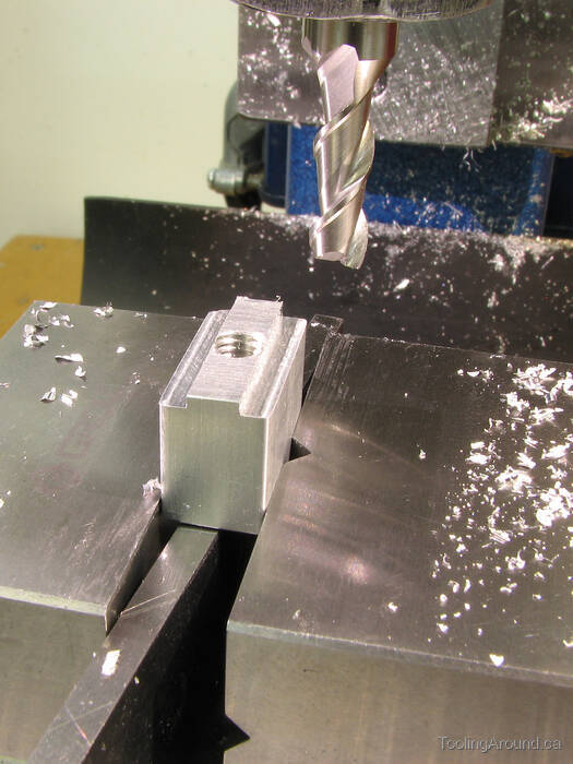
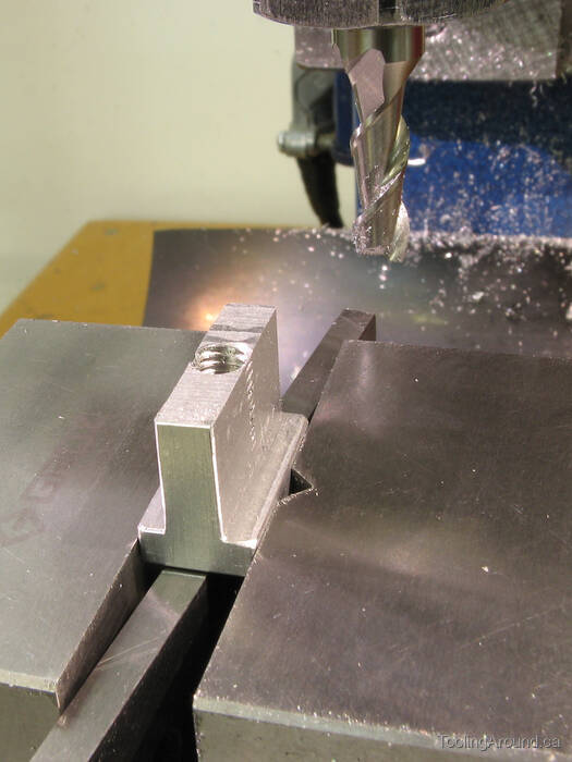
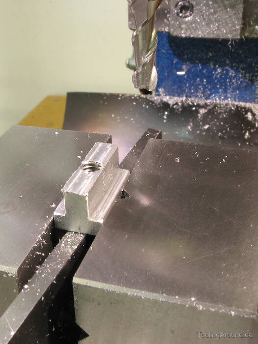
The back side of the body was milled to leave two tabs that would slip into the T-slot and keep the guide in a vertical position.
A slot was milled between the tabs, to accept the top of the T-nut.
To make the T-nut, a piece of scrap 3/8″×3/4″ aluminum was held in the vise and a hole was drilled and tapped for a 10-32 SHCS. This hole was positioned by careful measurement, to ensure that it was on the centre line of the T-nut.
Next, I milled one side of the nut, leaving it a bit wide. Then I reversed the nut in the vise and made the same cut on the other side. This ensured that the part of the nut that would go into the slot would be positioned exactly on centre. Finally, I measured the too-wide width and adjusted the table to cut to the correct width. After that, it was a simple matter of making the cut as deep as I wanted it, reversing the nut, again, and cutting the other side to the same depth.
Sometimes, I find it's safer to do something like this simple, mechanical spacing, rather than risking an error in arithmetic or inattention in repositioning the work piece.
Ordinarily, I would use steel for a T-nut, but this one will not see heavy use, nor will the clamping forces be very great.
Both sides of the T-nut have been machined, leaving a very tall T-nut. As you can see, the centre part of the nut is so narrow that the cap screw threads are showing.
Enough of the centre part of the nut was removed to allow it to project above the T-slot and into the slot in the back of the guide body (shown, above).
A front view of the guide, cleaned up for the photo.
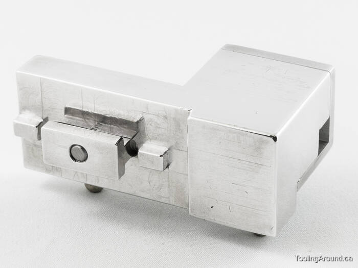
A back view, showing how the T-nut fits into the slot in the body. This keeps the nut positioned in line with the slot when positioning the guide for use.
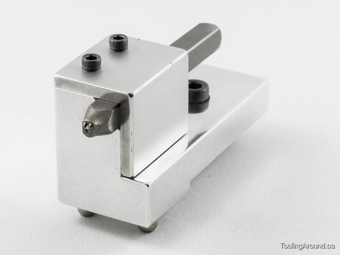
Finally, here's a stamp, posing in the guide.
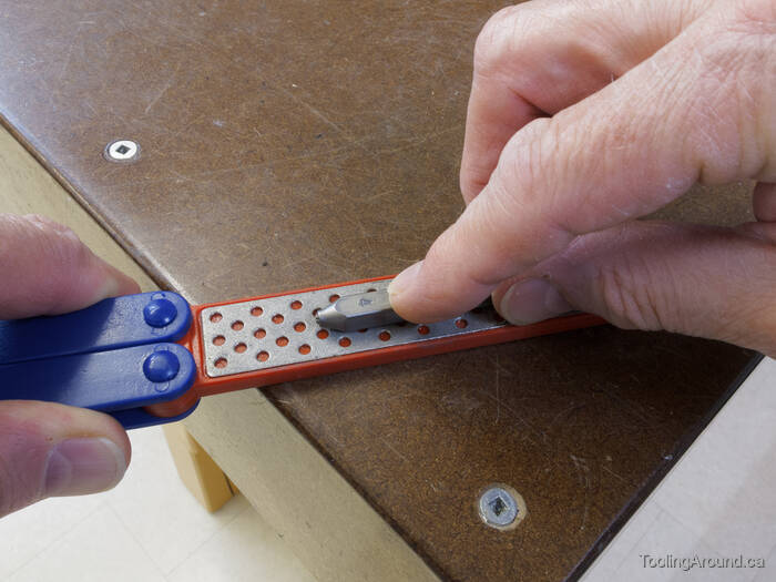
The stamps had just the tiniest bit of a burr near the business end. They're hardened, so filing them smooth was not an option. Instead, I rubbed each of the four sides of each stamp on a diamond sharpening stone. The close fit of the guide meant that, otherwise, they would snag on the inside of the guide.
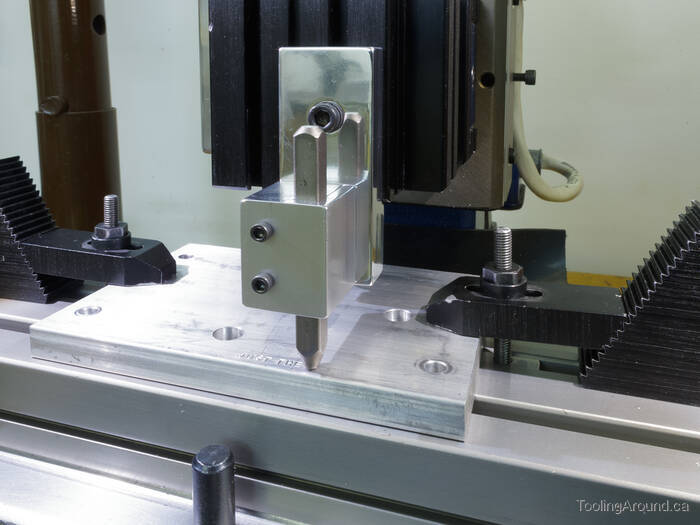
Here's the guide, being tested.
This is actually the second test. Initially, I had just a bit of slop in the fit of the stamps in the guide. I milled a bit off the top of the body, so the cover could drop down, and filed the holes in the cover so it could slide over. It was a matter of taking out a couple of thousandths of an inch, as the first test resulted in uneven letter positioning.
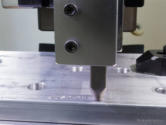
I moved the table in 0.090″ increments to position each letter.
Directly after stamping the letters, there's evidence of displaced metal, as it was forced aside and up. It isn't actually as bad as it looks in this photo—the letters are only 2mm high.
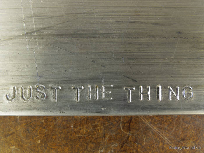
Despite taking care to tap the letter “I” more gently than the others, it is still too deep.
After several strokes with a fine file, the raised metal was removed and the letters look much better.
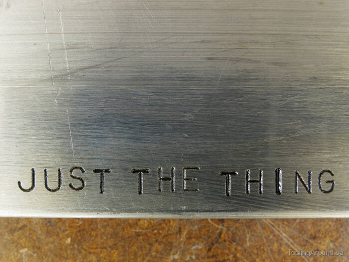
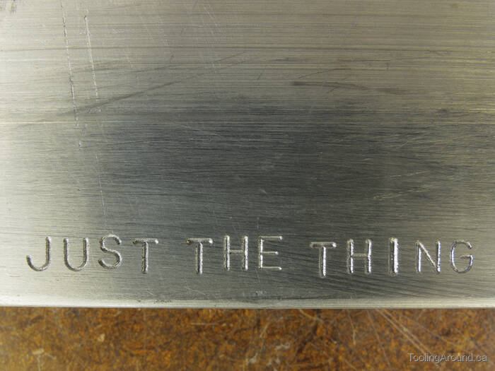
Finally, here's how they look with a bit of black paint wiped across the surface.
As you can see, the results are mixed. The horizontal spacing is consistent, although I should have placed the letters just a bit closer together. However, the vertical alignment is irregular. Why is this?
If you look at the two “TH” sequences, it's clear that the “T” is low in each case. And the letter “S” is high. I have not yet determined the source of the imprecision and whether it's because of the guide, my technique or the stamps themselves. If you decide to try this, I will be interested in your experiences.

Here's a drawing of the guide. Please use the drawing as just a suggestion. For example, you might choose to make the body longer, so it will project further below the spindle nose.