 Tooling Around
Taig Mill – Sherline Motor Mount

I chose to “go vertical” in my design of a motor mount for the mill and place the motor to the left of the headstock, with the pulley beneath. This is how the stock motor is mounted and I like it there. As to putting the speed control above the motor, well, it just seems like a good place for it.
The mount itself is simple. The concept was well proven when I had this motor on my Taig lathe, so I chose not to change it (except for moving it to the other side of the headstock). As you see, there's a motor-mounting plate and a mast to hold the speed control. The mast attaches to the backing plate on the speed control box. Less visible in this photo is the mounting bar, which is attached to the headstock T-slot. A pivot shaft protrudes from the end of this bar, through the plate and into a bearing that is attached to the plate. Finally, a screw with a ball handle permits adjustment of belt tension without tools. The speed control backing plate, bearing and ball handle are re-used from the earlier lathe mount.
Pulley Bushing (Skip to "Motor Plate".)
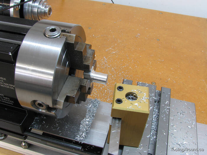
Here, I'm turning a test piece to exactly the diameter of the Sherline motor shaft, so I can check the diameter of the hole in the bushing as boring progresses.
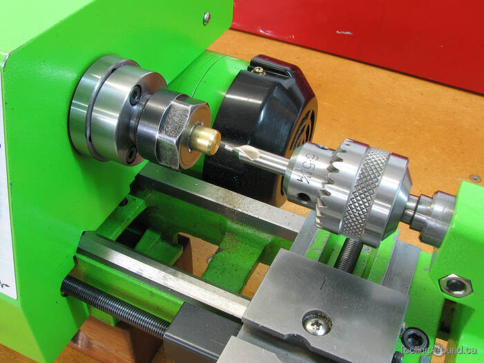
It happened that I had some brass rod of the correct diameter to fit the Taig mill pulley. In this photo, I'm preparing to drill and bore an adapter for the Sherline motor shaft.
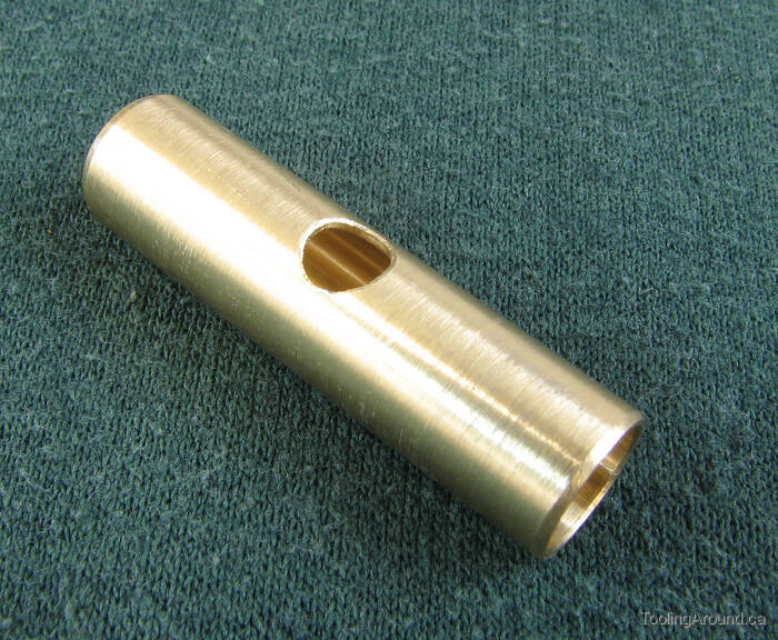
Here's the completed bushing, with a hole to clear the grub screw that holds the pulley on the shaft.
Motor Plate (Skip to "Controller Mast".)
The motor mounting plate is made of 1/4″ aluminum plate. As designed, there's nothing tricky about it, although it's important to mark out the holes for the motor mounting screws so the position of the motor will provide clearance for the power cord to bypass the mast without rubbing on it.
Note that the centre points for the two small-diameter arcs near the upper right of the photo lie outside the intended motor plate. This is good to note before roughing out the plate, as we'll want those centre points, later.

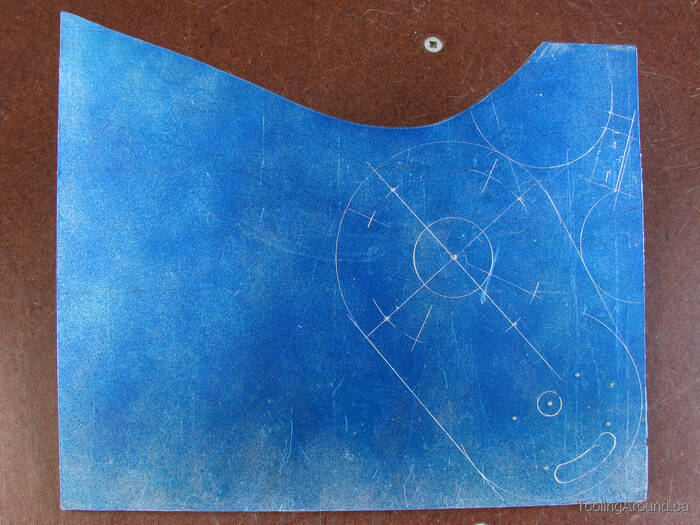
Here's a drawing of the plate. It's full-size, so you can trace it or at least mark out some points, if you want to make your own. This is the only drawing I made for this project.

The motor mounting plate has been roughly cut out on the bandsaw, removing a great deal of material that needn't be removed on the mill. The two strange projections near the upper right are there to preserve the centre points of the two small arcs.
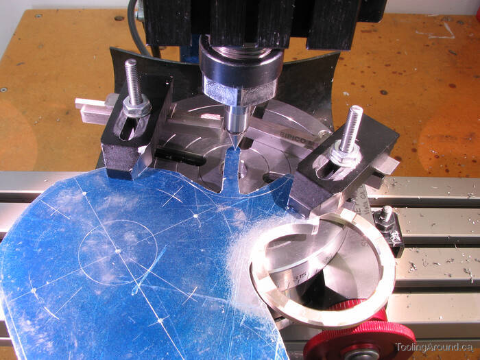
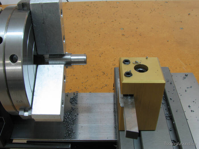
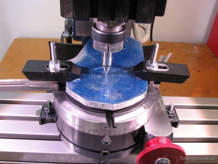
The plate is being positioned on the rotary table, to cut the second of the small arcs, described earlier. The table itself has already been centred under the mill spindle. Now, the arc's centre point is being centred under the spindle. The net result is to place the desired point on the workpiece on the rotary table's axis of rotation.
The ring projecting out from under the workpiece is a spacer. There's another one completely hidden under the plate. These rings were salvaged from a 5-1/4″ hard disk drive. I like using them because they are very precisely made to exactly the same thickness. Keeping the workpiece off the table means that I can mill right through the entire thickness without hitting the table.
Having centred the arc's centre point on the rotary table, the mill table was moved the required distance, that being the radius of the arc minus one half the diameter of the end mill. Then the arc was cut, as shown in this photo. You can see that the bit of aluminum holding the centre point of the arc will fall away.
The next step was to trim the straight edges of the mounting point for the mast.
Next, I trimmed the straight edges on the sides of the plate.
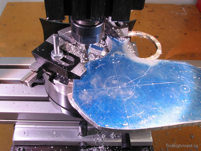
The first step in machining the motor mount end of the plate was to find the centre. All of the machining of this end of the plate is based on this point.
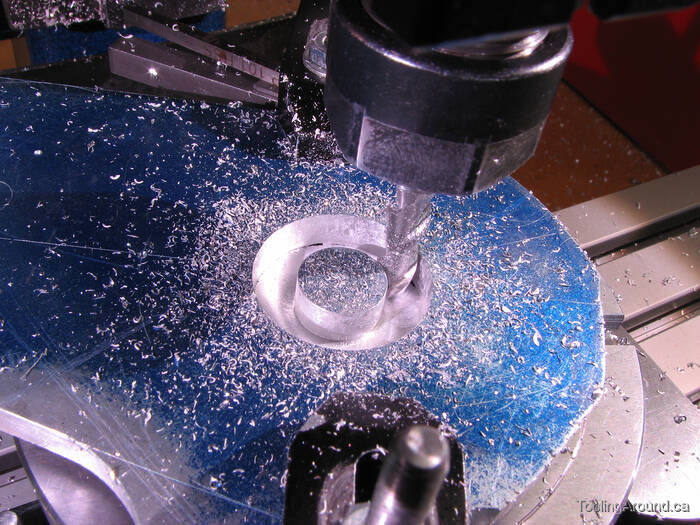
A hole to pass the motor shaft was cut by simply rotating the plate and gradually lowering the cutter until the hole was finished. One of those circular spacers is under the plate, keeping it clear of the table.
The hole doesn't have to be very big, but I made it about 1″ diameter.
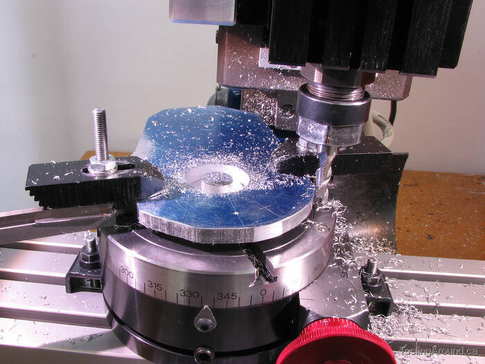
The large, outer arc nominally matches the diameter of the motor. The precise diameter doesn't matter – I just tried for a fair curve with the straight sides.

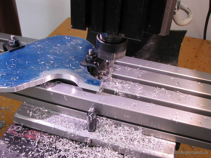
A similar approach was used to machine the small end.
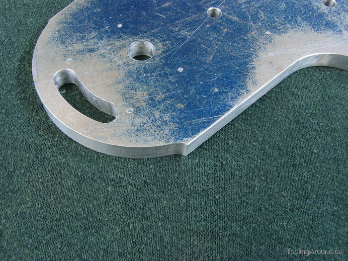
Because the hold-down clamps were in the way, I couldn't mill right to the straight edge, so a little bump remained at each end of the arc. This was just fine. In fact, even in situations where I could have completed an arc, I left a bit of a bump. This allowed me to use a file to make a fair transition from the curve to the straight edge at all four places where this was required.
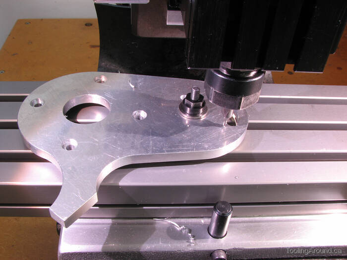
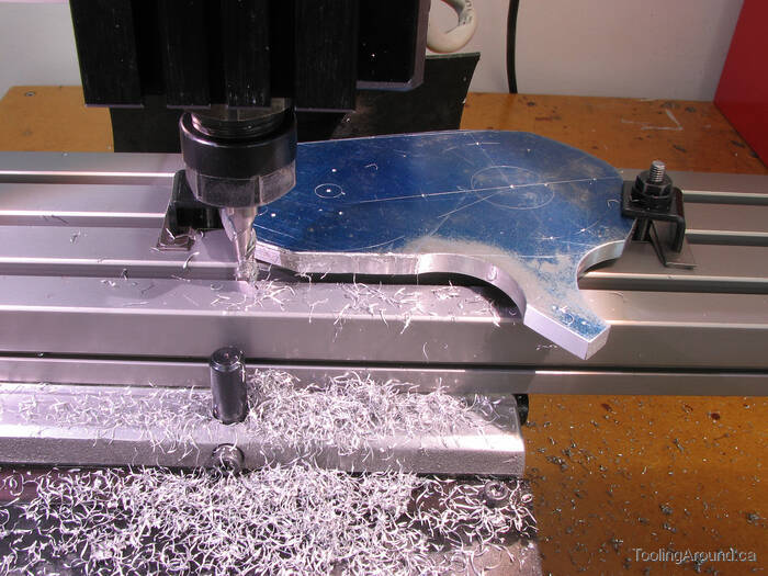
The plate was marked out on one side, but had to flipped over to make the screw holes for the pivot bearing. The reason was that they needed to be counterbored on the side opposite the counterbores for the motor mounting screws. After centring the workpiece by measuring from the pivot shaft hole, I slid a T-nut along the slot and under the hole. After inserting a stud, I fastened the plate to the T-nut and removed the step block clamps. The result, shown here, was a clear space in which to work to drill and counterbore the screw holes for attaching the bearing block.
Controller Mast (Skip to "Assembly".)
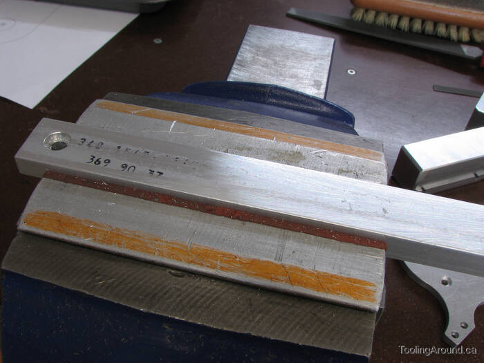
To make the speed control mast, I used a length of salvaged aluminum bar from my little stock pile. “Salvaged” is a word that means that it had seen prior use and bore the marks of that former life. In this case, that included some threaded holes, one of which would be visible in the completed mast. I decided to drill out the threaded hole and plug it. In this photo, I'm turning the plug from a scrap of the same bar.
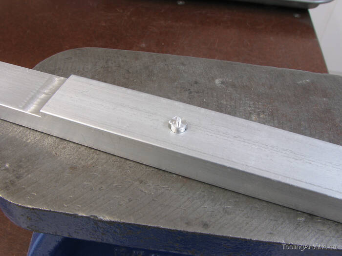
Here's the plug, inserted in the bar and sitting on a small anvil. Note that the hole has a small countersink. That's so the plug will have something to grip when it's peened over.
The plug has been peened over and is ready to file flush with the bar. Because the plug is made of the same material as the bar, it should be almost invisible when it's cleaned up.
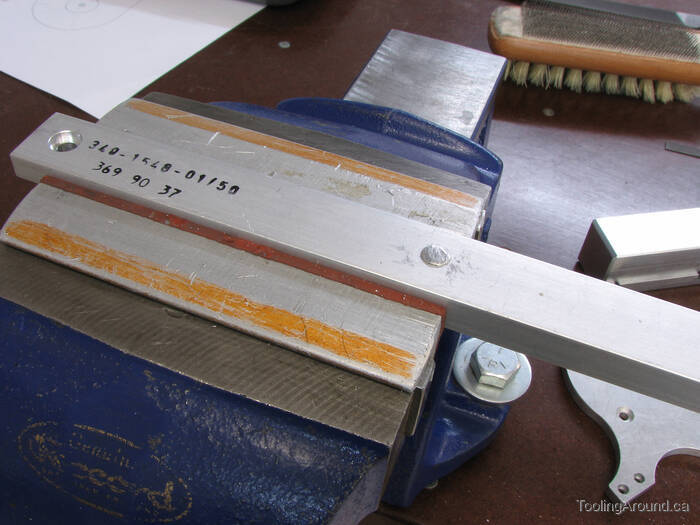
It almost worked, too. I think I was a bit enthusiastic, peening the plug, as the bar is marked up a bit from errant hammer blows. On the other hand, I didn't manage to completely fill the very edges of the hole. Ah, well, it's just cosmetic.
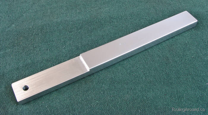
Here's the completed speed control mast. The rabbet is to keep the speed control backing plate aligned with the mast, as a single mounting screw was used.
Assembly (Skip to "Pilot Light".)

This is the mounting bar, with the pivot shaft sticking out the end. Most of one side of the bar was milled down, leaving a raised part that is a close fit in the headstock T-slot, thereby keeping the entire mount assembly aligned.
The pivot shaft was salvaged from a gas-charged strut that held up the liftgate window on our Jeep. It's unhardened steel, ground very smooth and round.
This is the pivot bearing, used previously when I mounted this motor on the lathe.
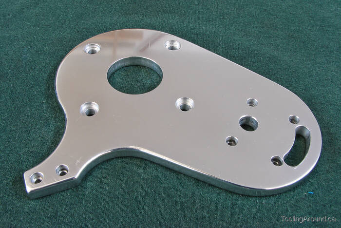
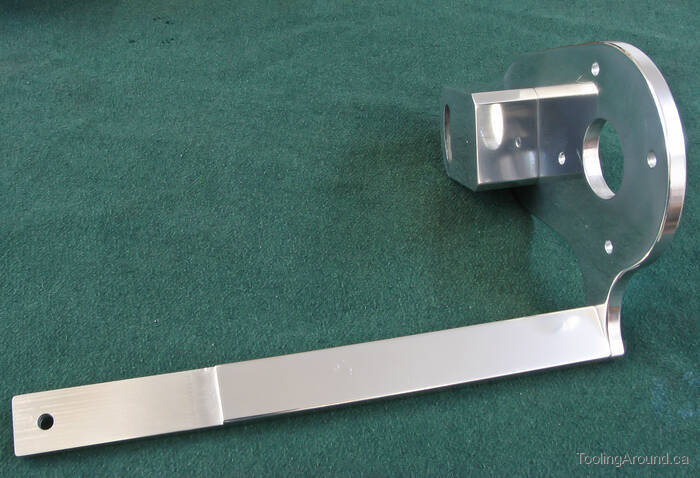
This is the completed motor mount plate. It cleaned up very nicely.
Here are the three parts of the motor mount assembly, well, assembled.
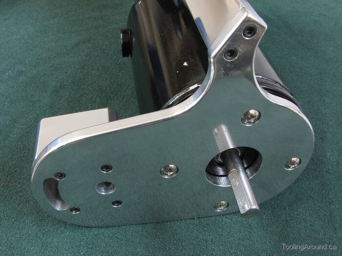
This is the motor end of the completed mount, motor and speed control assembly. As you can see, the controller mast is attached using two 14-40 SHCSs, with their heads flush with the plate.
This is how the speed control is attached to the mast.
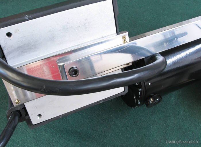
Notice how close the control-to-motor cord comes to the mast. This was deliberate and is the result of taking care when drilling the holes for the screws that attach the motor to its plate. The motor needed to be rotated just the right amount.
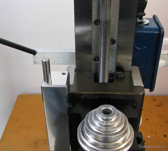
This is how the mounting post is attached to the headstock. There's room to move it up or down to align the pulleys.

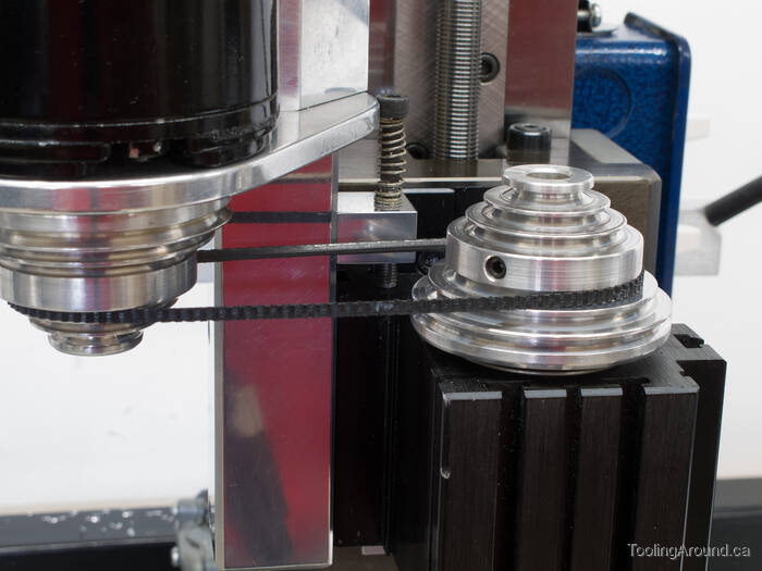
Here's the completed installation. It's very quick indeed to adjust belt tension.
A washer was required (under the brass one) to adjust the position of the ball handle, so it would be able to swing enough for tightening and loosening without fouling the mill column.
Pilot Light (Skip to "Height Adjustment Screw".)
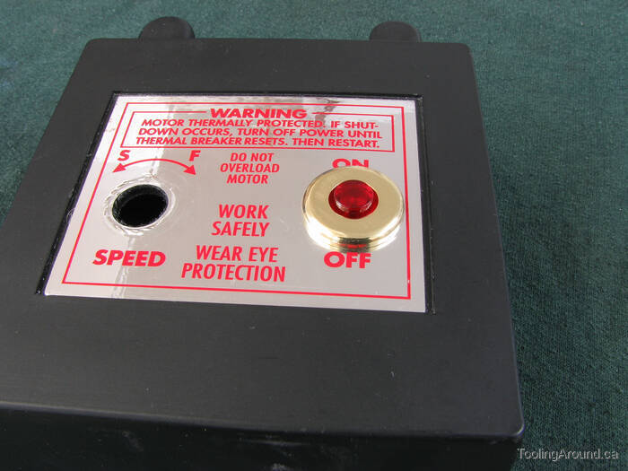
Since the speed control was plugged into the same place where the stock motor had been connected, the toggle switch on the speed control was redundant. (Either that, or the one I had just installed in the switch box on the column was redundant.) Anyway, I decided that a pilot light would be more useful on the speed control than the now-redundant toggle switch.
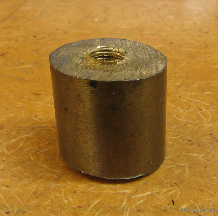
It hardly looks it, but this bit of scrap contains a nice bezel for a pilot light. Hindsight being what it is, aluminum would probably have been a better choice, to go with the silvery reflective label in the speed control. Oh, well.
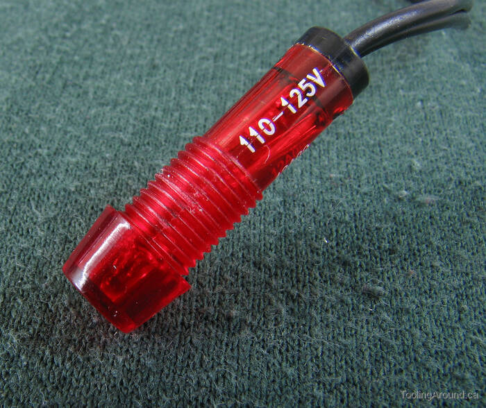
The pilot light is a simple neon bulb that I could simply wire into the line connection. Physically, the challenge was that the threaded portion is too short to accommodate the thickness of the speed control case and a washer on each side. On the other hand, the diameter of the pilot light is small enough to fit through the toggle switch hole and still have space around its perimeter. This observation led to the design af the bezel.
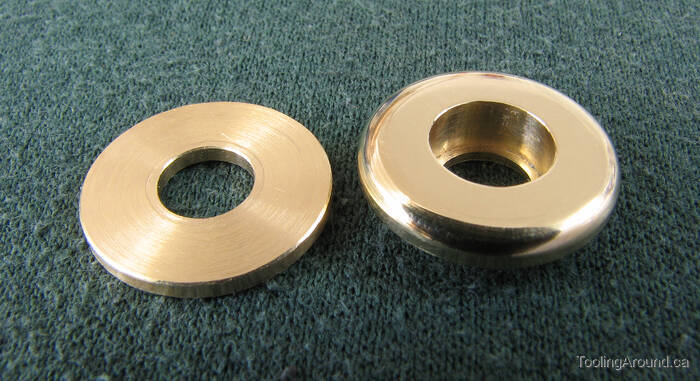
On the left is the washer, which will be used on the inside of the box.On the right is the bezel. The diameter of the hole fits the threaded part of the pilot light and the recessed part allows it to sit deep enough for the threaded portion to suffice.
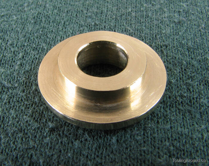
The outer diameter of the bezel fits the toggle switch hole.
When installed, the pilot light was considerably recessed, but with just enough protruding to make it nicely visible.
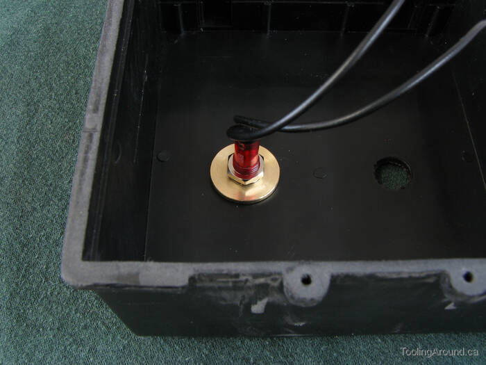
As you can see, there's plenty of thread to attach the pilot light.
Height Adjustment Screw
Quite some time after making this motor mount (years, actually), I decided to address a niggling concern by providing the means for making fine adjustments to the vertical position of the motor mount, relative to the headstock. The drive belts work very well and are durable, provided that they are accurately aligned. So, I added an adjustment screw to make this easier.
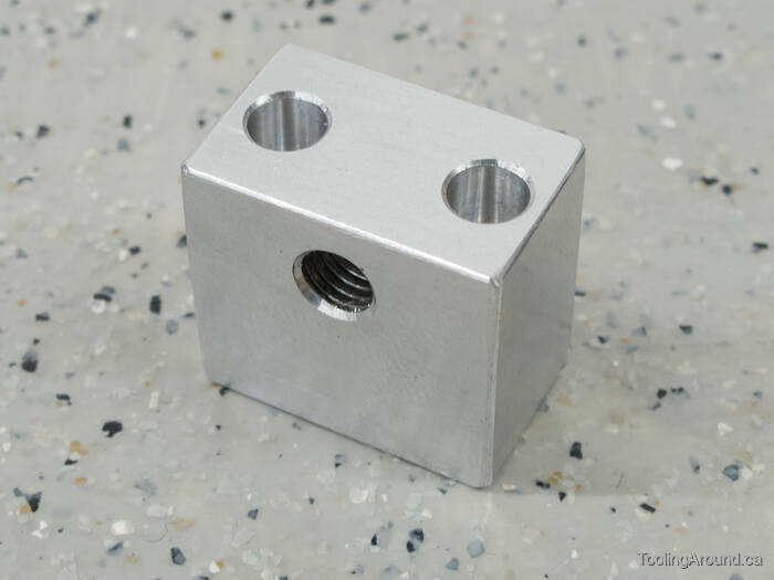
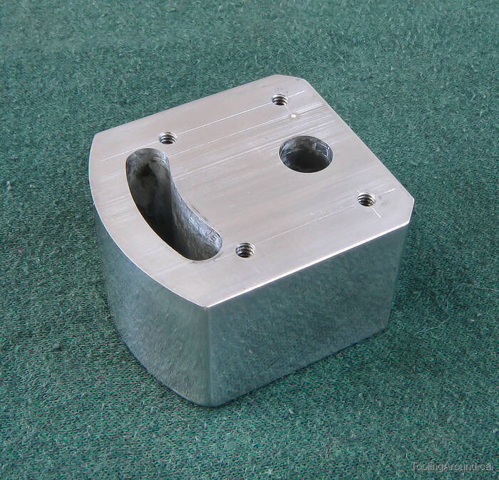
The body is an aluminum block, with a hole drilled and tapped for a 6-32 SHCS. The other two holes are drilled, counterbored and tapped for two 14-40 SHCSs.
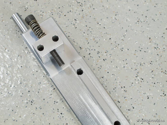
And here it is, attached to the mounting bar.
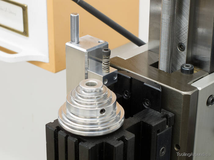
It nestles in there, almost but not quite touching the headstock dovetail mount. The spring should help the screw resist vibrating loose.
Now the height adjustment is easier to adjust precisely.