 Tooling Around
Taig Lathe – Sherline Motor Mount
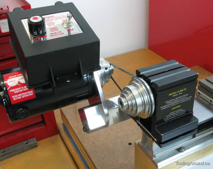
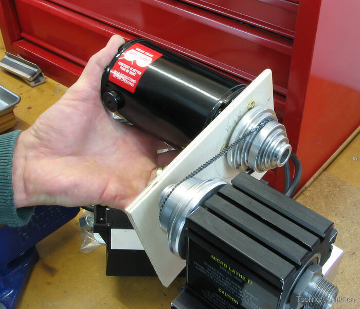
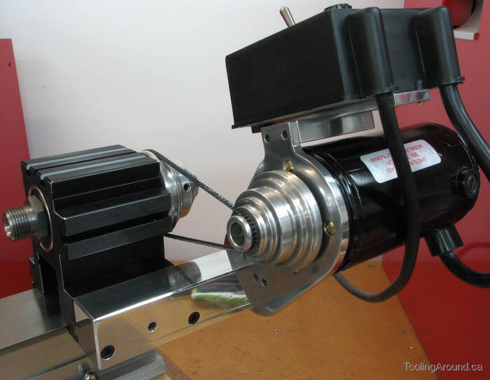
The Sherline motor and controller are an excellent match to the Taig lathe. This is hardly surprising, as the Taig and Sherline lathes are similar in size.
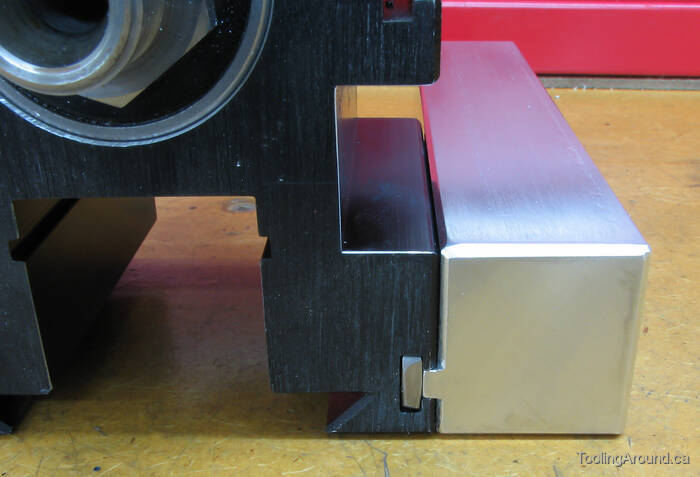
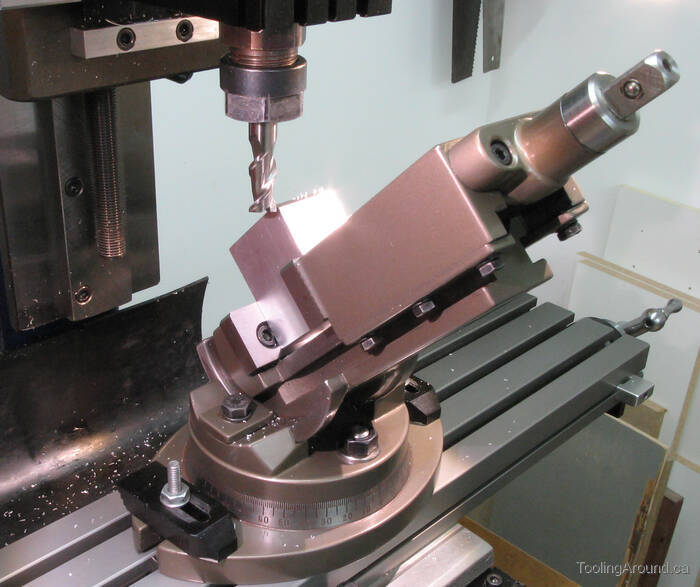
Although the Sherline motor mount can be attached directly to the Taig headstock, I chose to make a mount of my own design. In the photograph (above), you can see that a SHCS is used to fix the mount in position. As you will read (below), this was a temporary expedient, replaced by a ball handle adjusting screw.
Mounting Bar (Skip to "Pulley Bushing".)
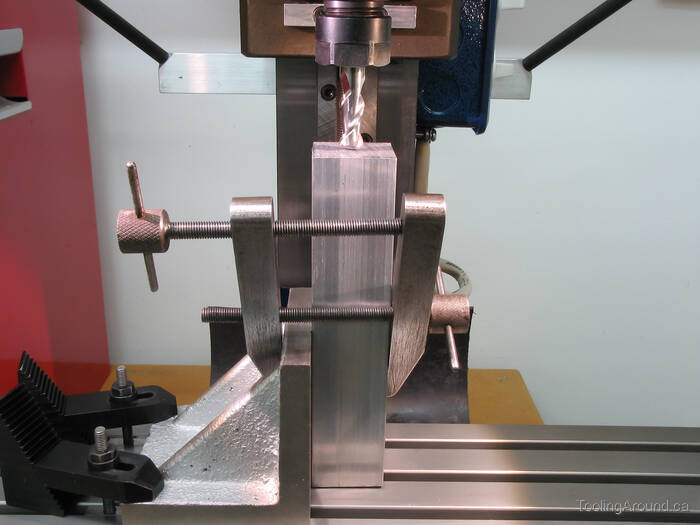
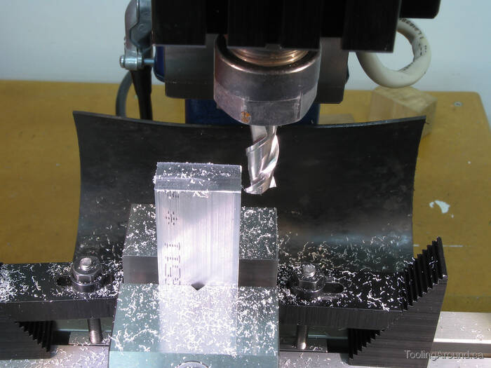
This is the workholding I used to face the end of the mounting bar. It seemed to me that gripping just the end of the bar in a vise would not have been sufficiently rigid.
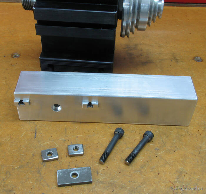
This mounting bar attaches to the lower T-slot on the back of the headstock. The two protrusions locate the bar on each side of the headstock clamp. They were formed, of course, by milling away all of the side of the bar that wasn't a protrusion.
The nuts were cut down from a couple of Taig-supplied nuts that were shipped with the mill.
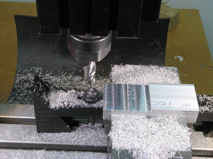
The middle hole provides access to the headstock mounting screw. It's counter-bored on the back side of the mounting bar to provide some space for the SHCS when the headstock is adjusted or removed.
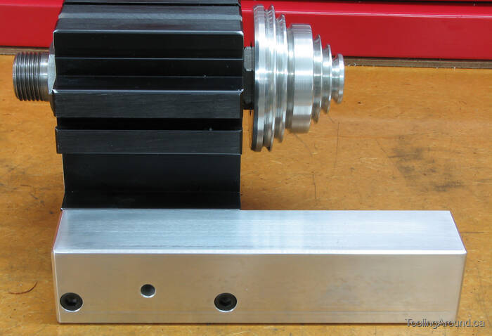
The mounting bar is attached to the headstock, showing the access hole for tightening the headstock clamp.
Here you can see the locating tabs that keep the mounting bar aligned.

Here's how the headstock clamp is tightened.
Pulley Bushing (Skip to "Controller Mount".)
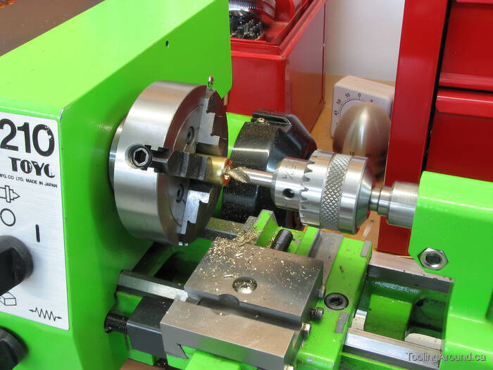
The Toyo lathe was used to make a bushing to adapt the Taig 1/2″ pulley to the Sherline motor.
What can I say? The Taig lathe was temporarily out of commission.
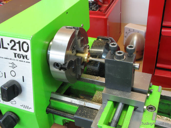
After drilling, the bushing was bored to size.
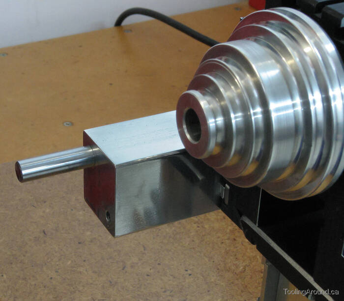
The bushing was made from a short length of 1/2″ brass round, which was a good fit in the Taig pulley. I centred it carefully in the four-jaw chuck, so the pulley wouldn't wobble when it was on the motor shaft. However, I was only partly successful, as there was a very slight vibration, in use. It would have been better to start with a larger brass round and turn it down to fit the pulley, followed by boring for the motor shaft without disturbing the setup in the chuck. That approach would guarantee concentricity between the turned outside surface and the bored inside surface.
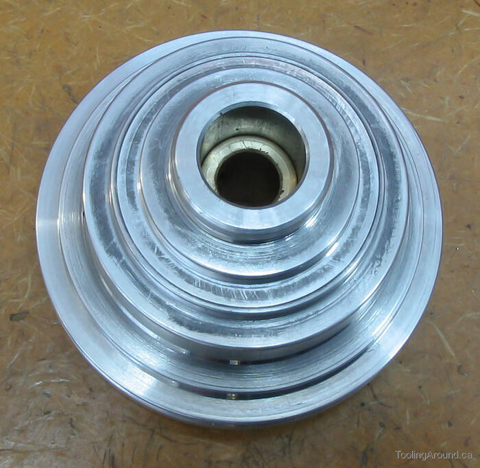
The bushing in the Taig pulley. It's recessed because the Sherline motor shaft is a bit short for this pulley.
Controller Mount (Skip to "Motor Plate".)
This is not the best way to square the end of part of the speed controller mount. Now that I know better, I understand that it's generally better to use the flutes on the side of an end mill cutter, not the tip. So, in this case, it would have been better to hold the workpiece horizontally in the vice (as in the next photo) and use the side of the cutter to mill the entire width of the workpiece in each pass.
I cut a rabbet in the post, to accept the controller cross bar. This was so I could use a single mounting screw to attach the two parts, with the rabbet keeping the cross bar from rotating about the mounting screw.
The post and cross bar are clamped together on a scrap of plywood backing. This is to ensure that, while they are positioned as they are meant to be held, the mounting holes will be precisely aligned. It was a simple matter to drill a hole of the correct diameter to thread, all the way through both pieces, then clearance drill the hole in the post and finally counter-bore the hole in the post, all without disturbing this setup.
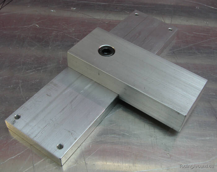
The assembled speed controller mount.
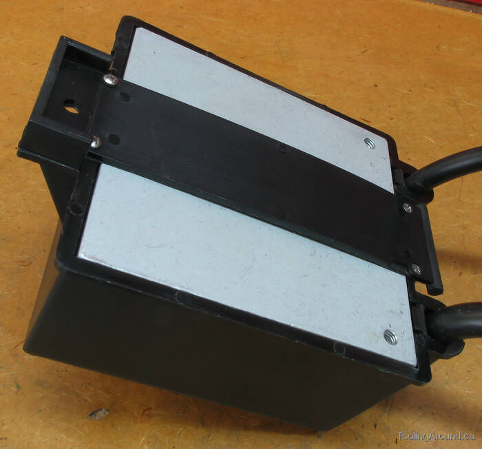
This is the original mounting plate, which uses short screws to attach the controller via holes in its cover.
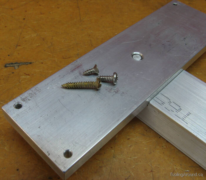
The short screws are the Sherline screws that attached the controller to its mounting plate. The longer screw is one of the wood screws that I had on hand and used to mount the controller to the new mounting plate.
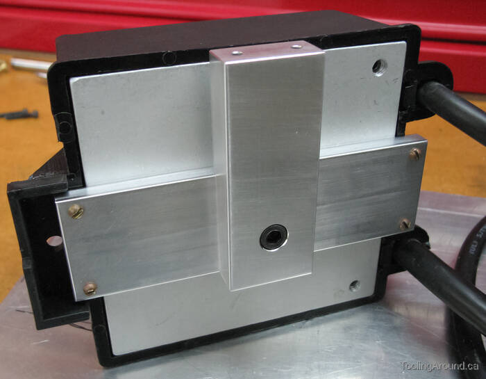
Here's the completed speed controller mount.
Motor Plate (Skip to "Bearing Block".)
This plywood mockup was used to check the fit and operation of the proposed motor mounting plate.
Holding the plywood mockup of the proposed motor mounting plate to roughly check the fit.
The rough fit was promising, so I cleaned up the plywood motor mounting plate.
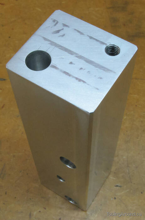
The mounting bar has a hole to accept a steel pivot pin and a threaded hole for the clamping bolt.
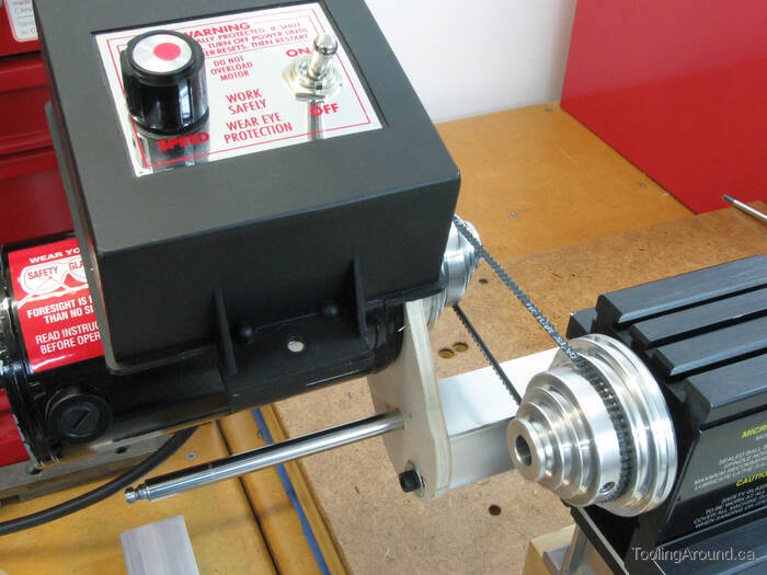
Using the plywood motor mounting plate, I was able to check that the mount operated as intended and that the angle of the speed controller was correct.
The motor mount pivot will be made from this nice-looking rod. It was salvaged from a gas-charged strut that held up the liftgate window on our Jeep.
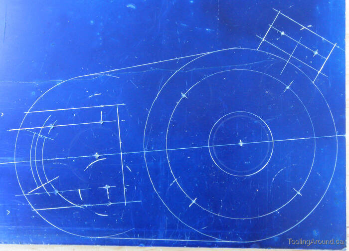
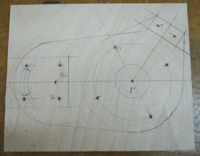
The motor mounting plate is marked out on 1/4″ aluminum plate.
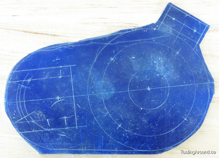
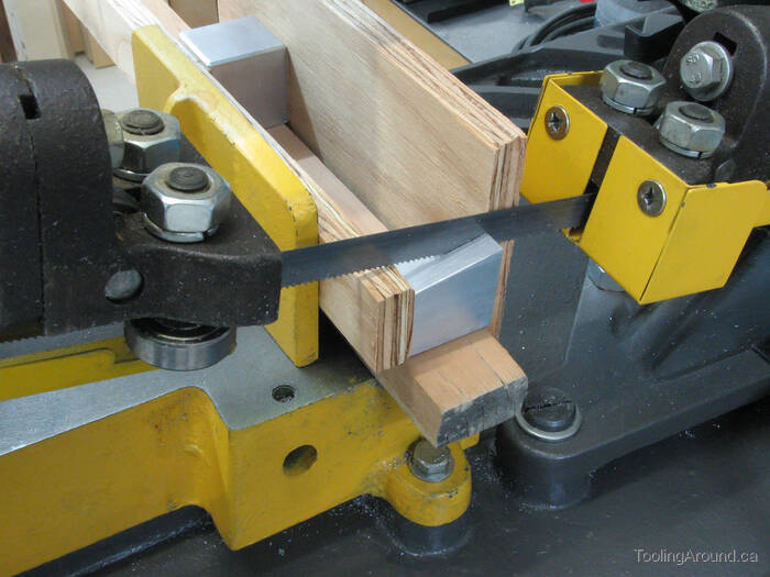
A metal cutting band saw is a wonderful time saver. By using it tilted up in the vertical position, with its table attached, I was able to remove much of the waste before using end mills on the mill.
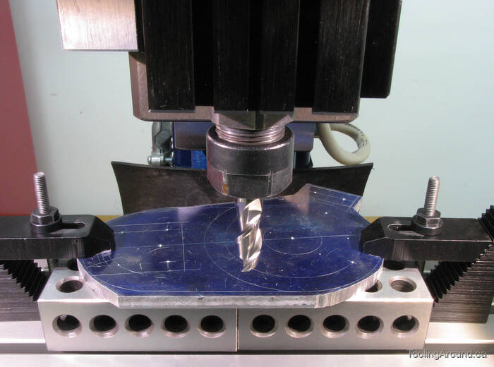
Preparing to mill one of the straight sides of the plate.
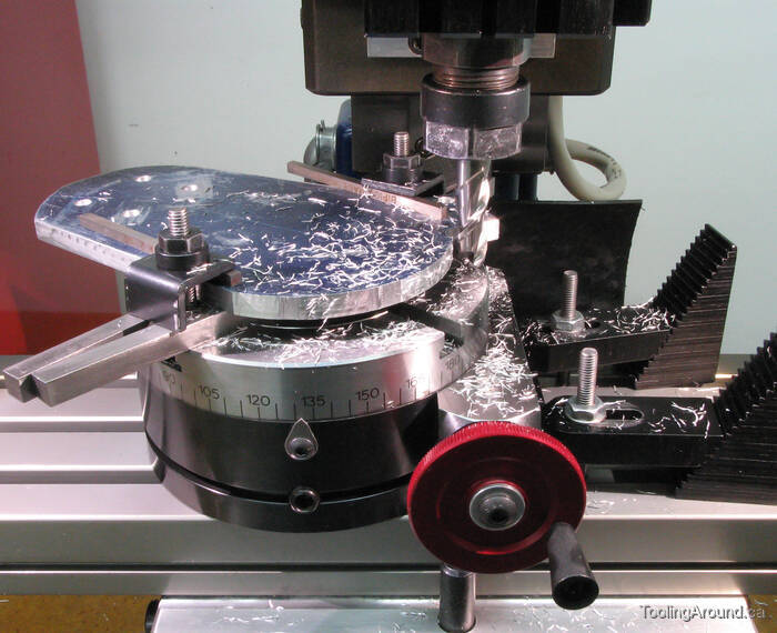
Next, I cut the large end of the plate, to match the diameter of the motor.
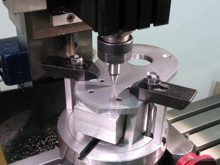
The setup for this cut was pretty much at the limit of the rotary table's capacity. The clamps are cantilevered out past the edge of the table, on lathe tool blanks that I used for packing.
Still using this setup, I cut the hole through which the motor's shaft will pass, and the holes for the screws that will hold the motor to the plate.
Bearing Block
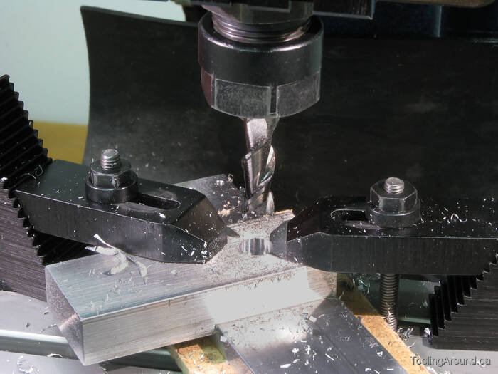
A bearing block will be attached to one end of the motor mounting plate. A hole in this block will accept the shaft on which the assembly will pivot. In this photo, I'm chamfering a corner of the bearing block.
Cutting small pieces sometimes requires odd setups. These pieces will be packing for a setup on the rotary table.
The setup to mill the end of the motor mount. The motor mounting plate has been attached to the bearing block, using 4-40 SHCS. After positioning the assembly so it's centred where the shaft hole is to go, the holes were drilled. Then the mill table was moved and the end of the motor mount plate and bearing block were milled together to the appropriate radius.
The mounting bar with the pivot shaft.
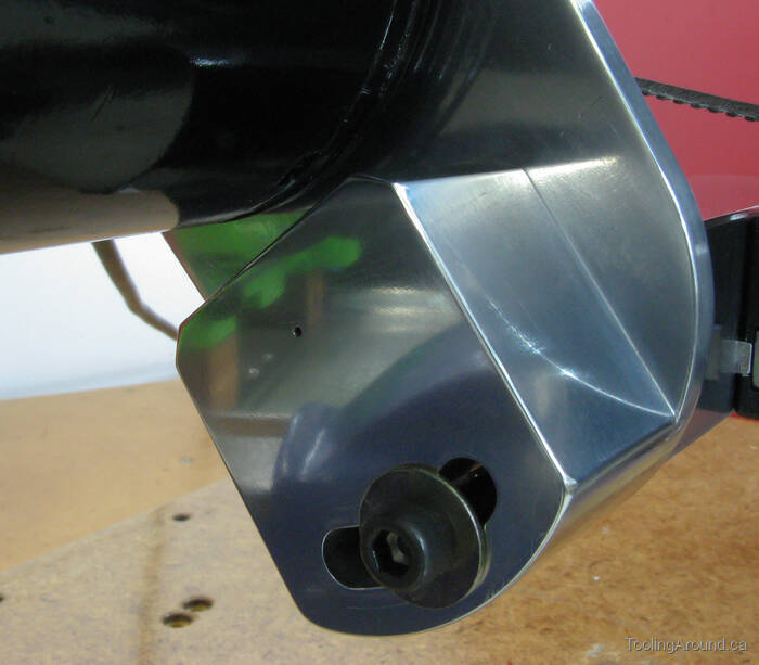
The hole in the bearing block lets air escape when sliding the assembly on over the pivot shaft.
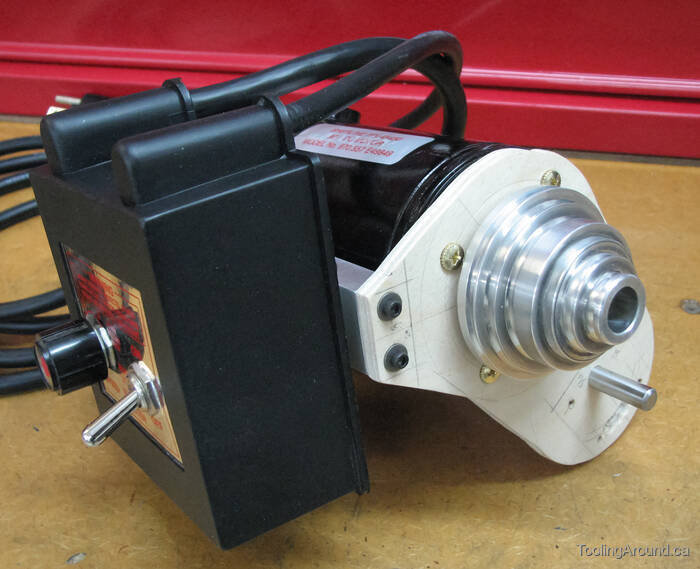
It's probably easiest to see the entire assembly from the back.
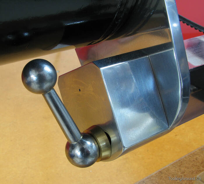
A ball handle makes it easy to change belt position or tension without using any tools.
I don't have photos of the making of this handle, but you can see the making of a similar one here.