 Tooling Around
Pulpit Lamp
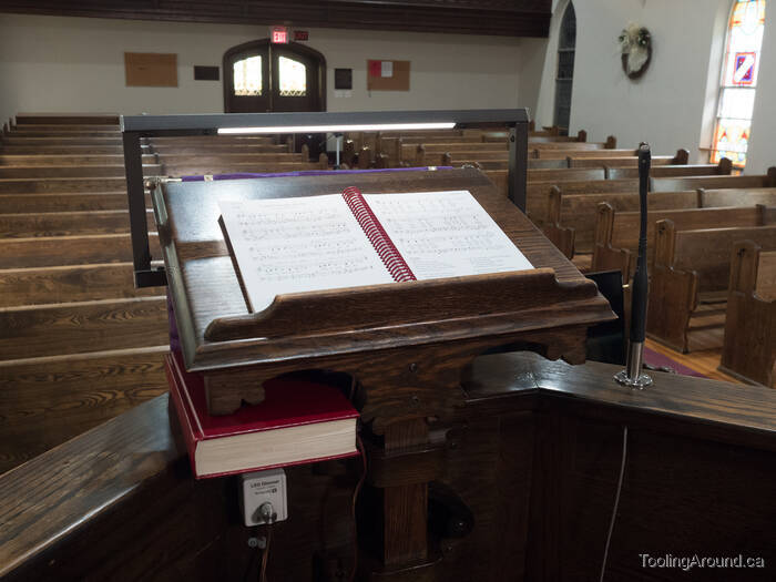
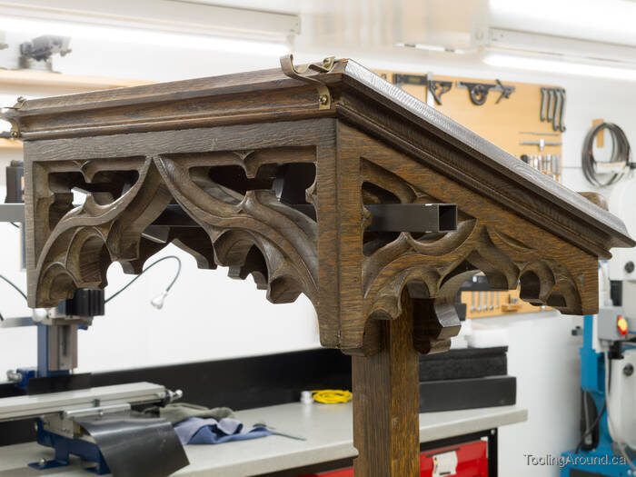
This is the simple lamp that I designed and constructed for the pulpit in our church. Although it looks simple, I think its construction was interesting enough to merit telling the story.
As you browse this page, if you find that you're puzzled about what's going on, a drawing may help. At the bottom of this web page, you'll find a link to the drawing that I made to help me think through this project before I built it. It may be helpful to have the drawing available in another browser tab as you explore this page.
Design Considerations (Skip to "Techniques".)
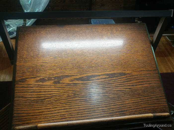
Before reading about "design considerations", consider the following two photos.
The easel height is adjustable. The implication is that the lamp must be attached to the easel itself, as otherwise its position relative to the easel will change as the easel's height changes.
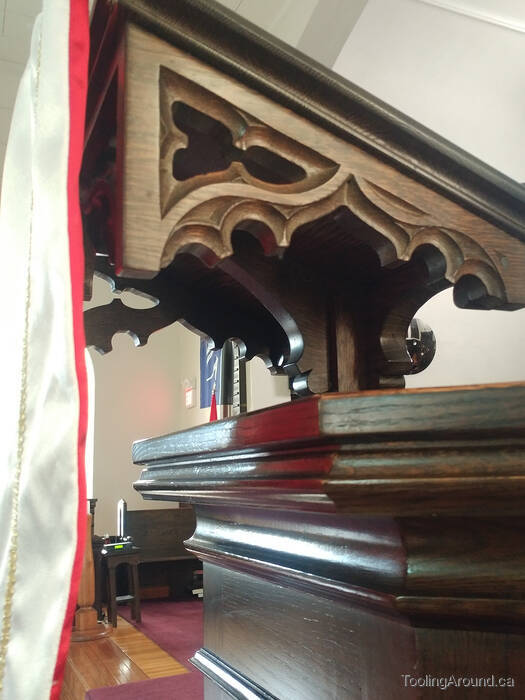
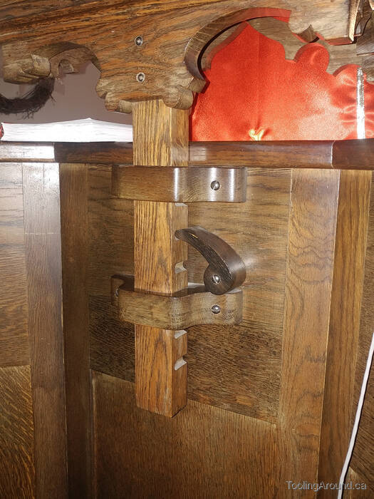
The decorative carving around the easel means that attaching a lamp is a bit challenging, especially as I didn't want to disfigure it in any way.
These are the things that I considered when designing the lamp.
- Safety
- It's no accident that safety is first in the list. The first concern is electrical power, which I have addressed by using a commercially-available power supply. Its output is low voltage and low current, much like any mobile phone phone charger (12VDC vs. 5VDC and only max. 8W). The other concern is that mitred corners would be sharp, unless they were rounded off, but filing them would remove the powder coat and leave me with a bit of a mess. It seemed better to make the joiners a bit of a "decorative feature" and deliberately expose them at the corners.
- Appearance
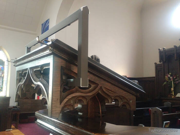
- To a reasonable extent, the lamp should not draw attention to itself. This is difficult, since the lamp is right there in front of a speaker. I did what I could to make it as plain as possible. More importantly, I took great care to make sure that the light from the lamp cannot be seen from anywhere in the audience. Light does reflect from papers on the easel to a speaker's face, of course, and there's not much to be done about that.
- Effective
- Material placed on the easel should be clearly visible. I addressed this by aiming the light at the centre of the easel and providing a dimmer control so the speaker can set the desired light intensity.
- Unobtrusive
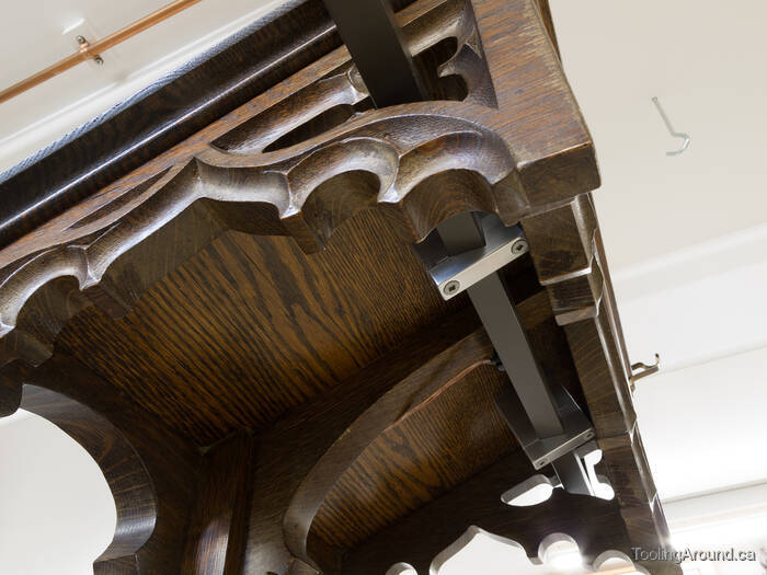
- The lamp must not be in the speaker's way, as they move papers about, gesture with their hands and so on. I addressed this by mounting the lamp well forward on the easel, with no attachment to the easel's sides or top surface.
- Respect
- It's about respect for the furniture that's already in place. Specifically, if the lamp is removed, it shouldn't leave behind any scars that were inflicted when it was installed. That's why the mounting hardware is on the underside of the easel, where the empty screw holes would only be seen by careful examination.
- Cost
- I was able to keep the cost down by using materials that I had in my shop, so I only purchased a bit of LED tape, a power supply and a dimmer control.
- Service Life
- Any maintenance that may be required during the lamp's service life should be simple. Disassembly for service should be easy, even if the service person has no prior knowledge of how the lamp is made. Spare parts should be readily available for the foreseeable future. The only fasteners are button head machine screws and wood screws for mounting to the easel. Electrical components consist of a simple power supply and dimmer and some LED tape.
Techniques (Skip to "Top Tube".)
Rather than mention some things over and over, I'll describe them here and you can accept them as given on the rest of this page. These are just my usual practice on the mill and are not specific to this project.
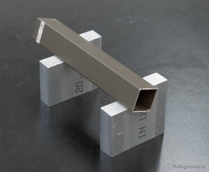
When we had a new deck built behind our house, I kept some surplus pickets. They're made of 3/4″square aluminum tube, with a wall thickness of about 0.045″. Eventually, I realized that they might be suitable for a pulpit lamp, especially since they already had a brown powder-coated finish that might look alright against the pulpit's stained wood finish.
Wherever I used button head screws to attach tubing to joiners, I first drilled clearance holes in the tubing. Then I slid the tubing onto the joiner to determine where to drill and tap the screw hole. This was simpler than measuring to find the location of the tapped hole on the joiner.
Because the four tubes form a rectangle, it's important that opposite sides have exactly the same length. This is more important than making them some specific length and the obvious way to achieve this is to finish one end of a pair of tubes and then machine the other ends at the same time.
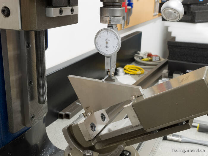
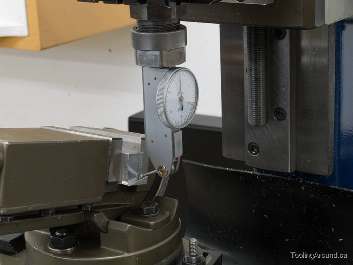
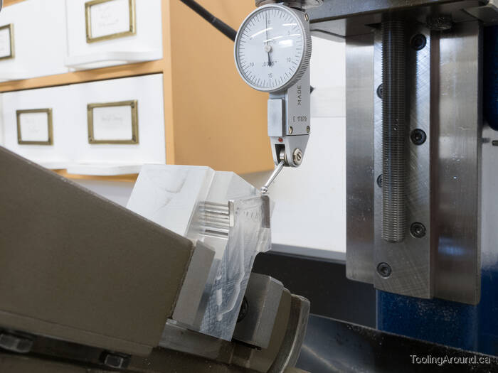
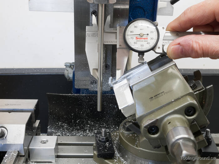
When aligning a vise's tilt, I use a DTI and sweep it across an angle block. The rare earth magnets keep the block from sliding off the vise.
When aligning a vise in a horizontal plane, I hold a precision square against the side of the mill table and put an angle block between the arm of the square and the vise body.
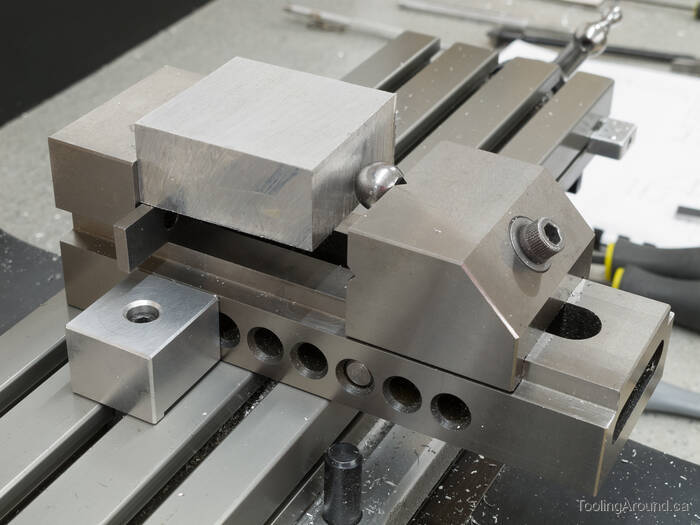
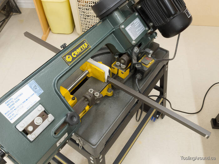
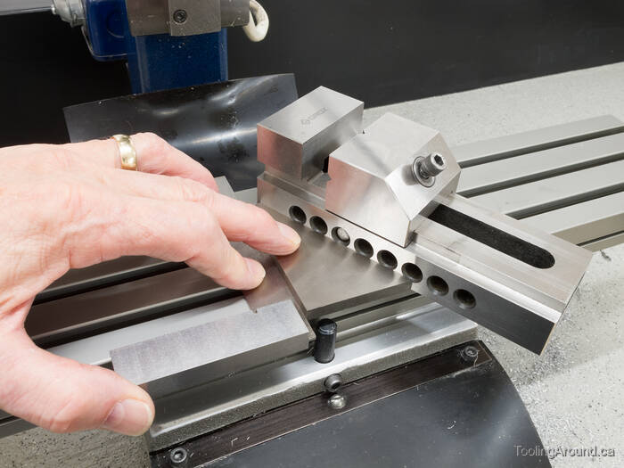
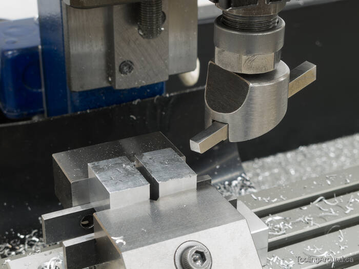
When squaring up a block that arrived fresh from the band saw, one challenge is to overcome the lack of parallelism of the sides to be held in the milling vise. I use a 1/2″ ball bearing with a roughly 0.35″ flat ground on it, placing the flat against the movable jaw face. This allows the opposite side of the work piece to sit nicely against the fixed jaw.
Top Tube (Skip to "Side Tubes".)
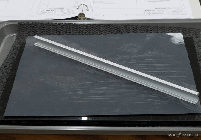
The top tube contains an aluminum channel that holds the LED tape, with an opening in one side to let the light out. It's not quite that simple, however, as the tube is tilted down, so as to direct the light to the middle of the easel.
This web page describes the second version of the lamp. The side tubes of the first version were too long, something that was only realized after it was installed. The top tube was too high and interfered with sight lines. So, I brought the lamp home and shortened the side tubes.
However, with shorter side tubes, the tilt of the top tube was incorrect because it was now directing the light too far forward on the easel. Rather than change the tilt, which would have required new joiners at the top corners, I decided to tilt the LED tape inside the tube. So, the top tube is tilted down 30° and the channel supporting the LED tape is tilted up 15°.
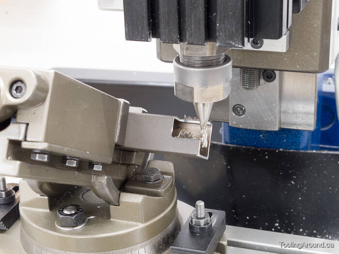
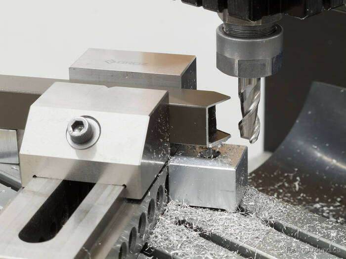
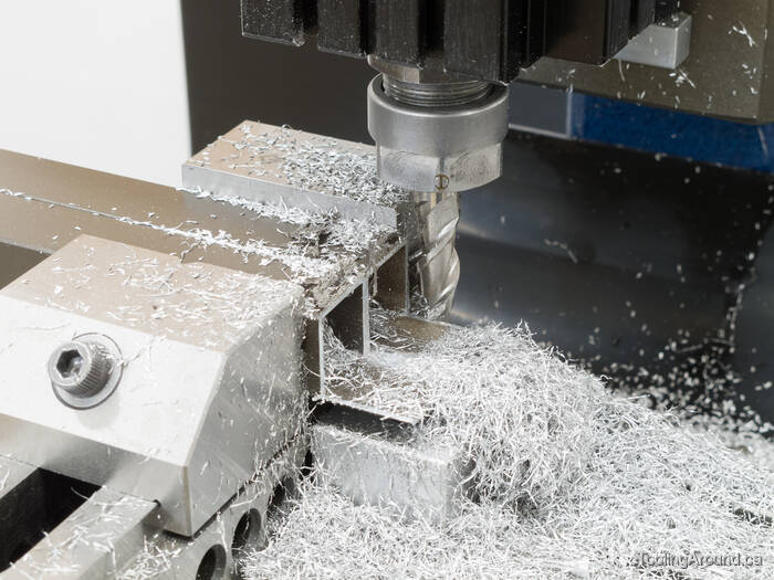
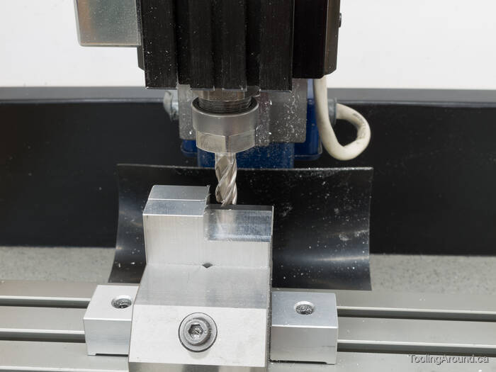
With the vise tilted 30°, I trimmed the ends to fit the corner joiners.
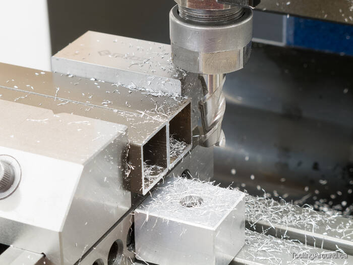
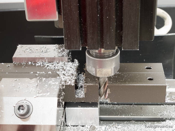
Then it was time to mill a slot to let the light out.
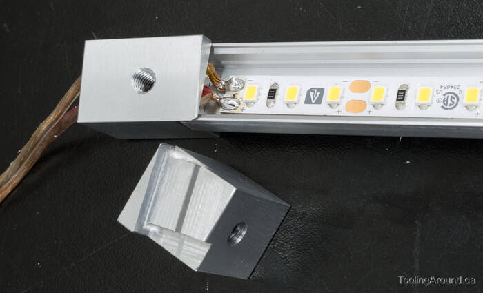
The next step was to prepare two mounting blocks for the channel that holds the LED tape. They are an easy sliding fit inside the top tube and long enough to accept a button head screw to secure them.
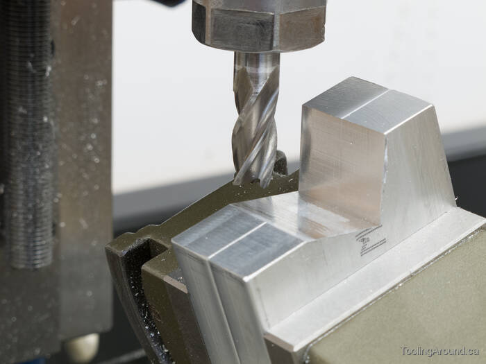
With the vise at a 15° angle, I cut the shape required to accept one end of the channel.
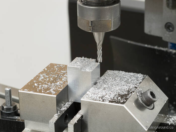
One of the blocks needed holes for electrical wiring.
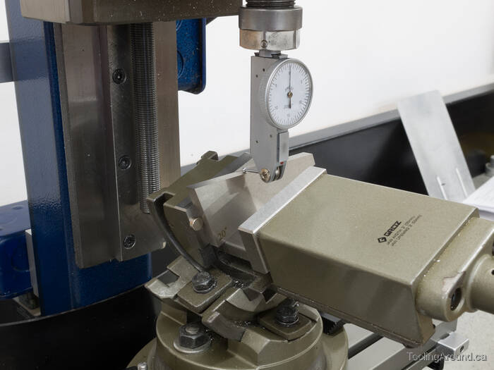
Now another vise was tilted to match the 15° angle of the mounting block, by sweeping a DTI across that part of the block.
The finishing touch was to cut a slot to accept the back side of the channel.
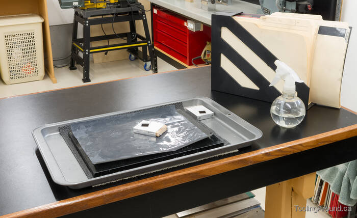
As it happens, the channel would only just slide inside the tube when it was upright and would not fit when it was tilted 15°. So, I did some careful filing down the length of the channel and refined the filed surface on abrasive paper sitting on a small piece of plate glass.
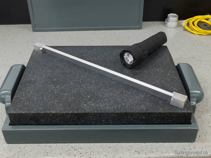
To make sure the channel was straight, I positioned it in the lamp supports, set it on a surface plate and used a flashlight to shine at the edge where the channel touches it. I knew I was done when no light shone through.
Side Tubes (Skip to "Top Joiners".)
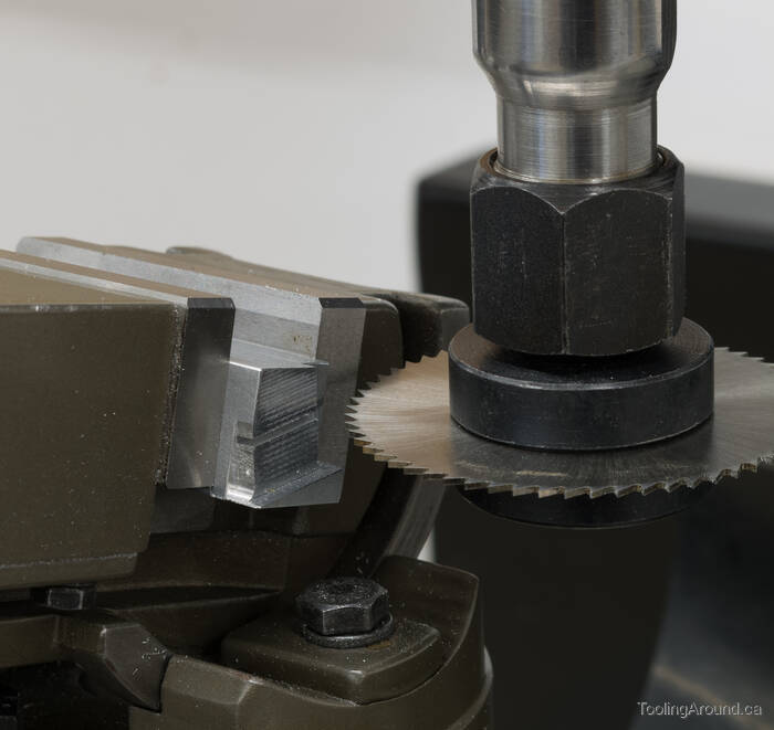
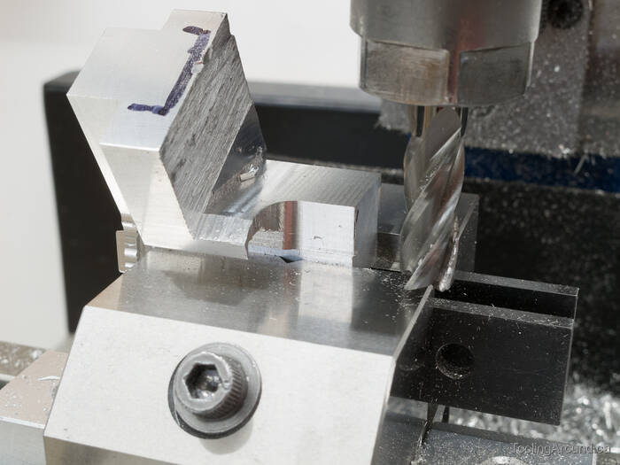
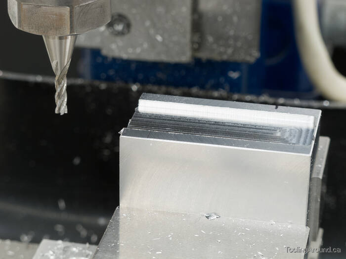
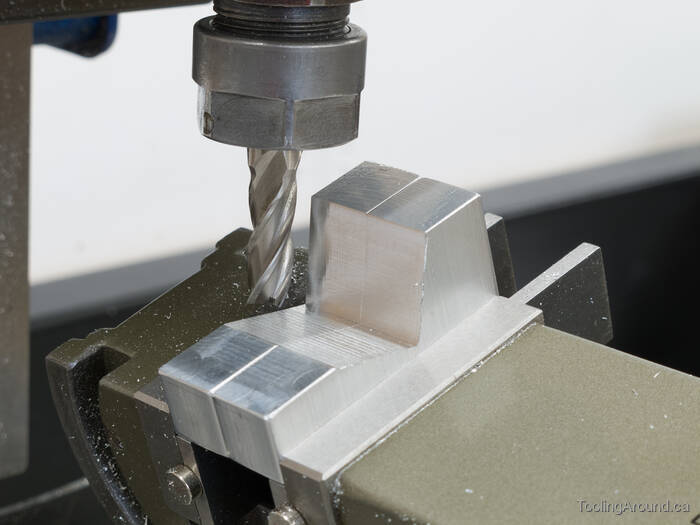
The top ends of the side tubes were cut with the vise turned 30°. They were a bit trickier to cut than the lower ends.
The first cuts form the outer side, which is on the bottom in this photo.
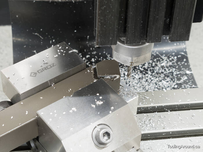
The second cuts form the inner side, which is essentially a notch that fits around the top tube.
The third cuts trim the remaining two sides for a close fit against the top tube.
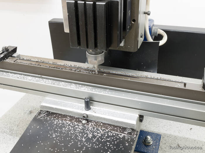
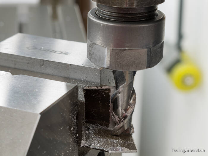
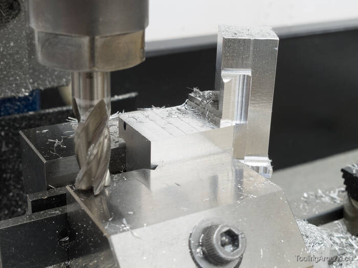
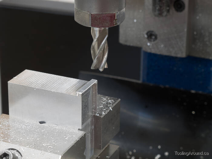
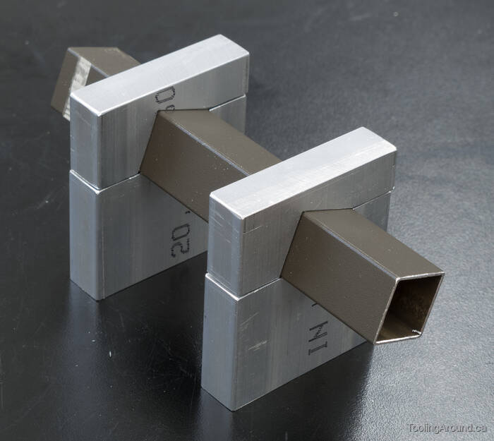
As mentioned earlier, the first version of this lamp had side tubes that were too long. This photo shows those longer side tubes being trimmed down to an appropriate length.
The first cuts shortened the overall length.
The second cuts trimmed three sides of the tube to the correct length.
Top Joiners (Skip to "Bottom Joiners".)
For me, these pieces were a bit of a challenge. Conceptually, I knew what I wanted to make. Making a CAD drawing of the parts helped me turn a concept into a design, but I hadn't thought through the exact order of operations or how to manage work holding as machining progressed.
What I actually did was start by finishing one surface and as much of its adjoining surfaces as I could reach without changing the setup. Then I would take advantage of such parallel sides as were then available by gripping them in a vise and finishing another surface (and its adjoining surfaces). I tried to think ahead to avoid getting into a situation where I would be stuck and, before I quite knew what had happened, it was done.
If that sounds like a tentative approach, well, it pretty much was. The following photos show some of it, but may be a little hard to follow. In that case, scroll down to the end of the topic to see the finished joiners and then scroll back up to see how I got there. My challenge was that I couldn't "scroll ahead to the future" to see what I wanted to produce before I made it!
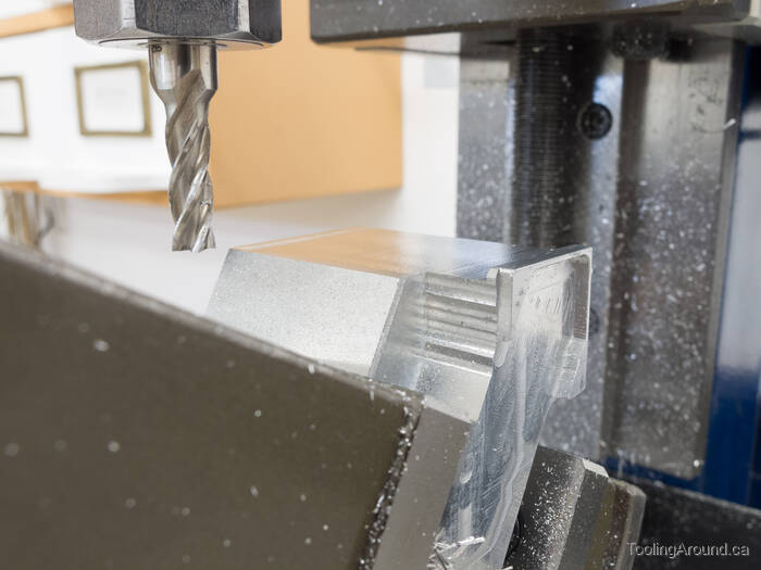
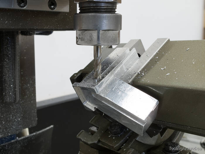
I started by milling out the outer surface of the joiner. The pointed tip of the side tube would slip into this space. Using a larger cutter to make the work faster, I stopped short of the finished edge of the "V".
With the vise angled 30°, I used a smaller cutter to finish the "V", so as to have a small radius at the tip. When fitting the side tube, I just filed the tube's sharp tip to fit the curved "V" recess on the joiner.
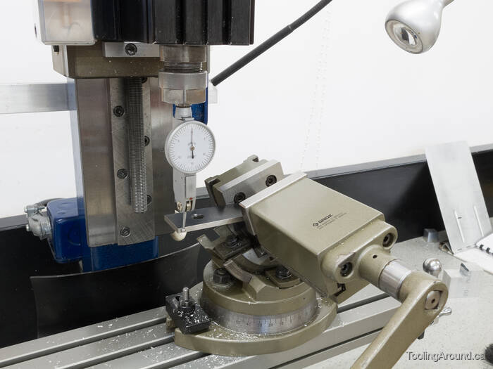
With the 30° surface defined, I switched to a tilting vise and swept the surface with a DTI to make sure that the tilt was correct.
That squiggle on the joiner's side reminds me of damage left on a tree from a beetle chomping away under the bark. In this case, it was just me setting a small cutter a tad too low.
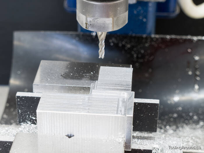
Now I could mill the surface that will match one side of the light bar.
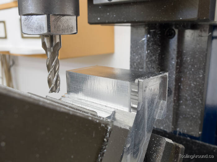
Using the same setup as much as I could, I finished the two surfaces adjoining the one I had just finished.
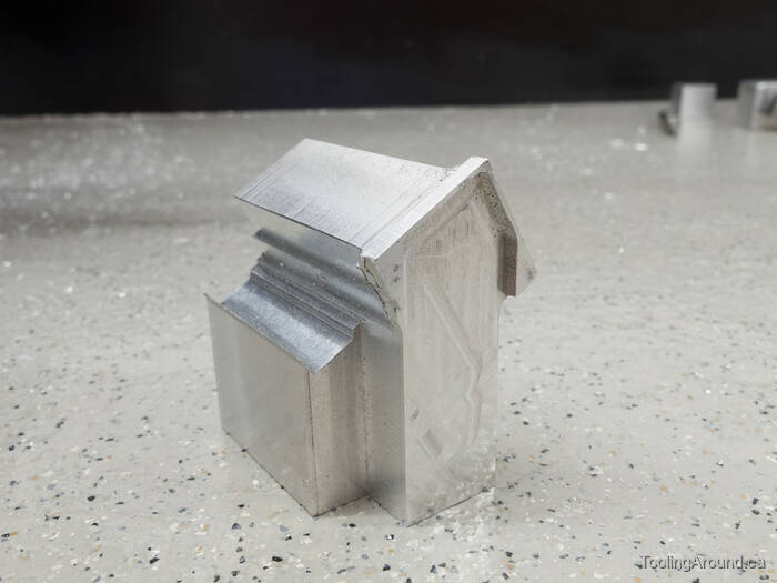
Standing upright, it now looked like this.
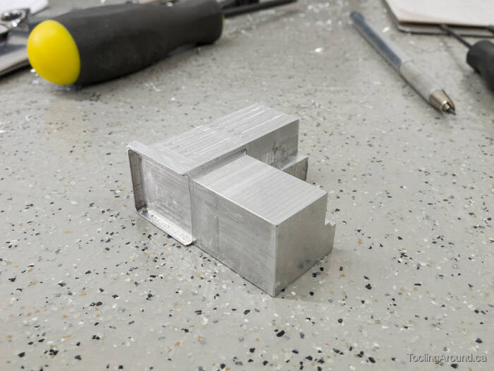
With three surfaces at least partially finished, I turned the part over and held it by two of those surfaces. Then I finished as much as I could reach of the fourth surface and the two adjoining surfaces.
And now you see the idea. I just kept gripping the joiner by finished sides, finishing whatever I could reach, until the joiners were done.
Once finished, it would have been possible to work out a more effective way to do this work, but that was no longer necessary. The ad hoc method worked fine, this time!
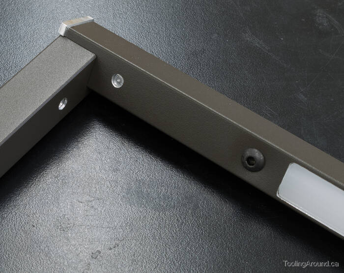
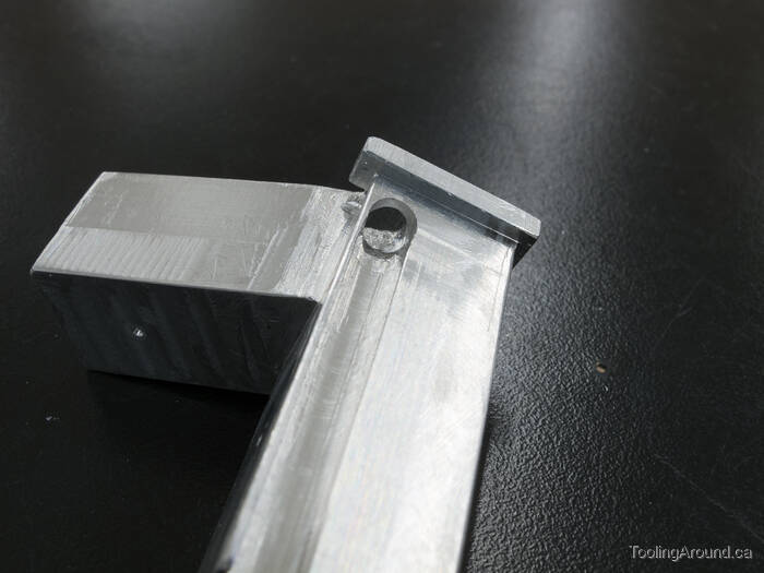
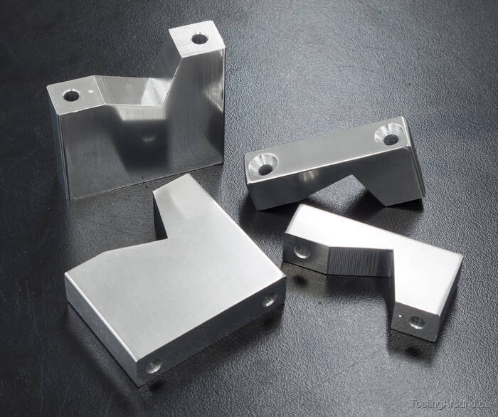
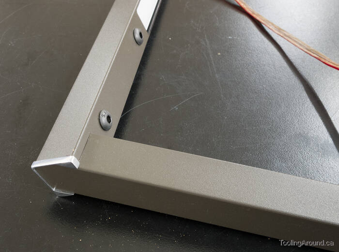
Here's how the top joiners look, assembled with the top and side tubes.
Bottom Joiners (Skip to "Joiner Wiring".)
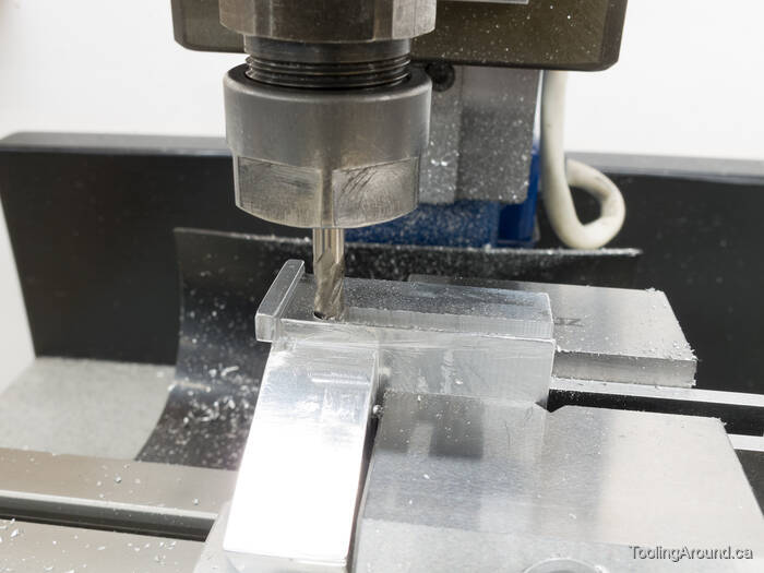
Making the bottom joiners was much like making the upper ones, in the sense that I milled away what I could, moved the part in the vise and repeated the process until it was done. The big difference, of course, is that there was no need to deal with an angled tube.
This is close to finishing with the outer surface, where a side tube will slide down into the pocket that's being formed.
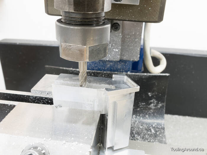
Here you can see that the pocket for the side tube and the bottom surface has just been finished.
Here are the front surfaces. Or maybe they're the rear surfaces, depending on whether this is the right hand joiner or the left one.
Once again, having finished what I could reach, I had a part that needed to be turned to another position to remove more material.
Eventually, the milling was done and I could cut this slot by hand, using a hacksaw and small files.
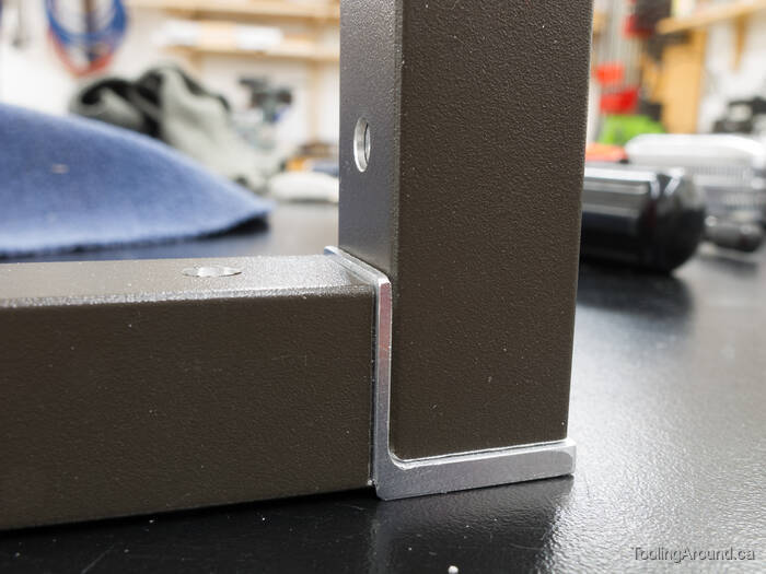
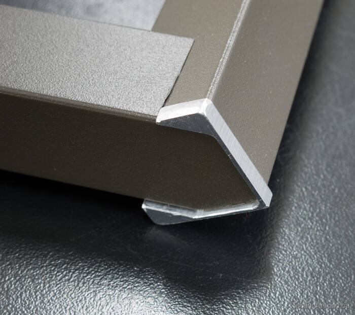
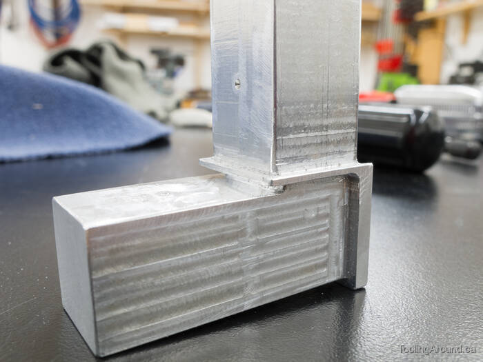
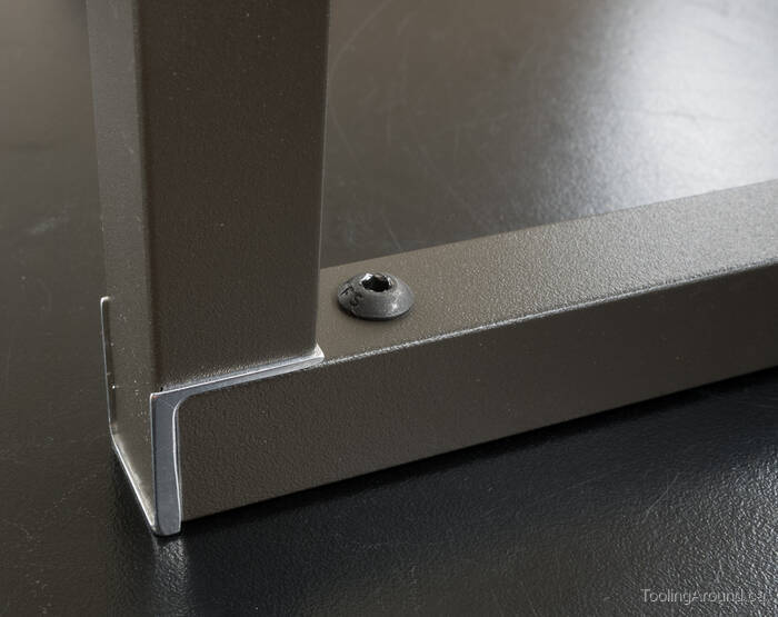
Here's a finished joint.
Joiner Wiring (Skip to "Supports".)
Wiring needs to pass through the top left and top right joiners, so I made provision for that after the joiners were otherwise finished.
First, I milled a slot in the top tube part of the joiner.
Then I put a slot in the side tube part.
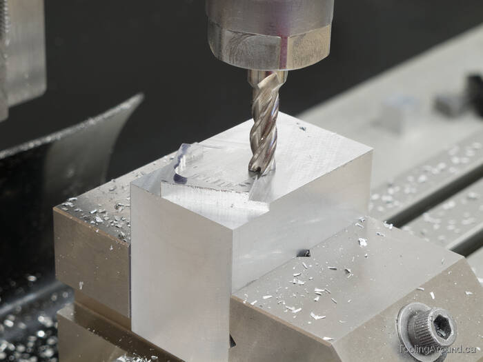
So far, so good, but now I needed to drill a hole that would connect the ends of the two slots. This, of course, presented an excellent opportunity to ruin the part, so I took great care to get it right, the first time.
Using a tilting vise that I can adjust on two axes, I set up the part so I could drill from the end of one slot to the end of the other. Rather than try to explain exactly how I did this, I'll just note that I held a straight length of tube in a collet as a reference. Visualizing the hole, I adjusted both tilts to approximate the hole that I had in mind. Then I measured the distance from the tube to the edge of both slots, adjusting the tilt of the vise until the measurement was the same for each slot. Next, I adjusted the other axis of the vise in the same way. This took a bit of vise adjustment and measurement until I convinced myself that all was well.
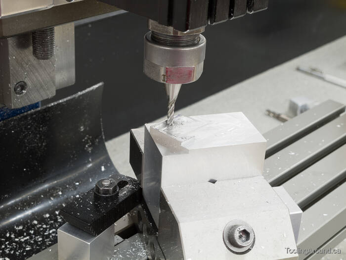
Then I used a milling cutter to make the hole, assured that it wouldn't wander.
Such a simple thing can be quite satisfying.
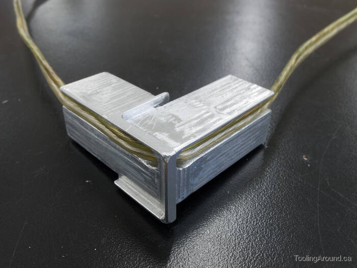
And there it is.
Supports (Skip to "Assembly".)
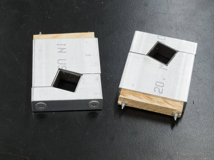
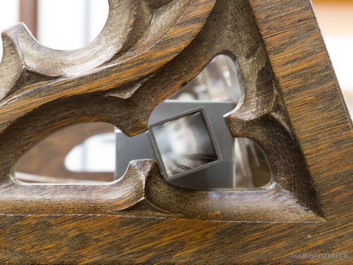
The supports and their caps grip the bottom tube, holding it in place under the easel. Because the easel slopes at a 20° angle, the supports have to hold the bottom tube at a corresponding angle, so the side tubes will be plumb.
In order to be able to install or remove the cap, the spaces between the cap and the support must meet at a corner edge of the bottom tube. No doubt that's as clear as mud, but the following photos will explain what I mean.
Because the supports and caps are identical to each another, I made them together, which was both easier to set up and a guarantee that they would match. The material is aluminum bar, 2×0.5″.
Here I'm milling the top faces of the supports, one being higher than the other because of the bottom tube's 20° tilt.
Using a DTI to sweep the top of an angle block to set the vise at 20°.
I held a parallel horizontally in the vise so I could sweep its edge to adjust the vise jaws to match the X axis. The screw holes in the vise jaw itself prevented me from simply sweeping the face of the jaw directly, so the parallel served as a proxy.
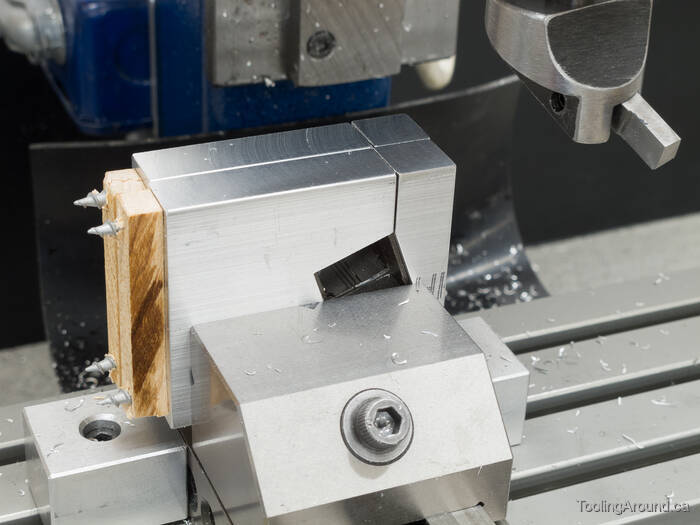
Then it was a simple matter to mill the space for the bottom tube.
A test fit with a scrap bit of tube looks alright.
I used the same setup to mill a space in the caps.
And the test setup is looking pretty good, now.
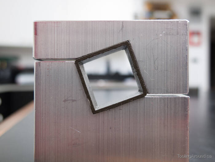
The gap between the support and its cap is just right for clamping and the corner edges of the tube are in the gaps.
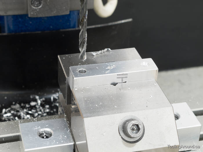
I drilled and countersunk screw holes in the caps.
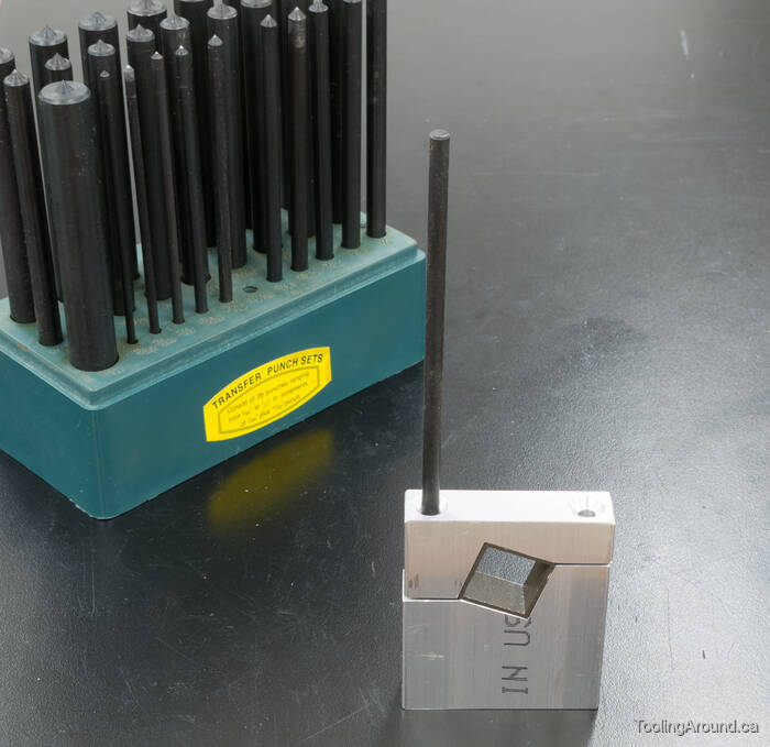
Then I used a transfer punch to mark the hole locations on the supports.
With short bits of tube in place, I ran screws through and into small scraps of wood.
Then I was able to fly cut the edges to make them match (a purely cosmetic step).
Might as well use a bit of abrasive paper on a piece of plate glass to make the sides shiny.
Remember the machinist's adage: "If you can't make it right, make it shiny."
Posing for a beauty shot.
Assembly (Skip to "Installation".)
After drilling and tapping holes in the tubes and joiners, it was time to put it together.
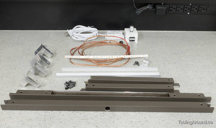
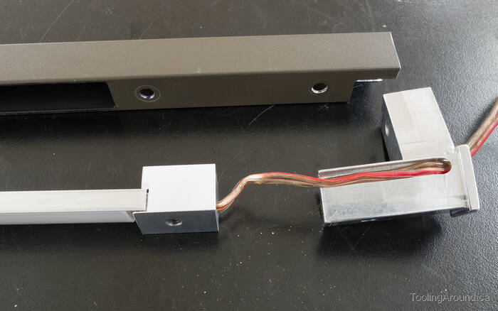
The components, including the power transformer and dimmer control in the background.
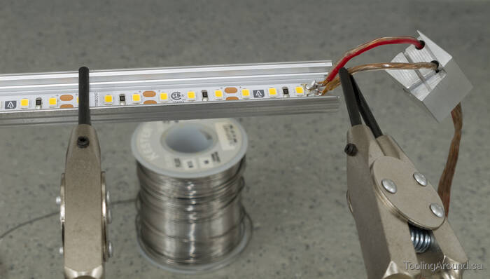
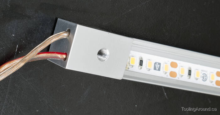
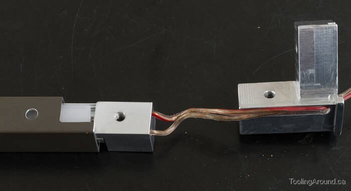
Let's start by attaching the power cord.
Here's the left-side channel support in place.
Looks good on the other side, too.
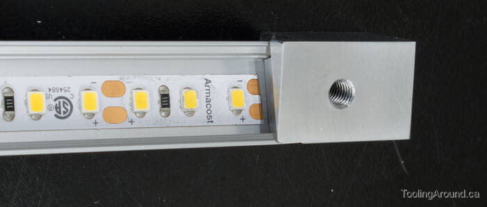
And this is the right side.
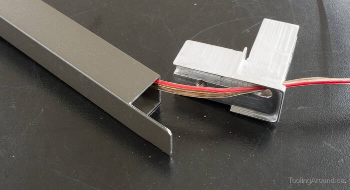
Pull the wire through the top left joiner.
Slide the assembly into the top tube.
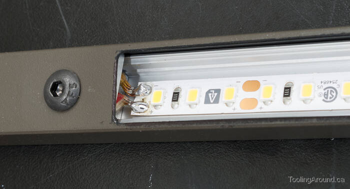
The channel is in place. A plastic diffuser will be snapped into place to protect the LED tape and spread the light appropriately.
I used a black marker to darken the shiny edges of the slot in the top tube. This wasn't terribly effective, but the edges are hardly noticeable now that the lamp's installed.
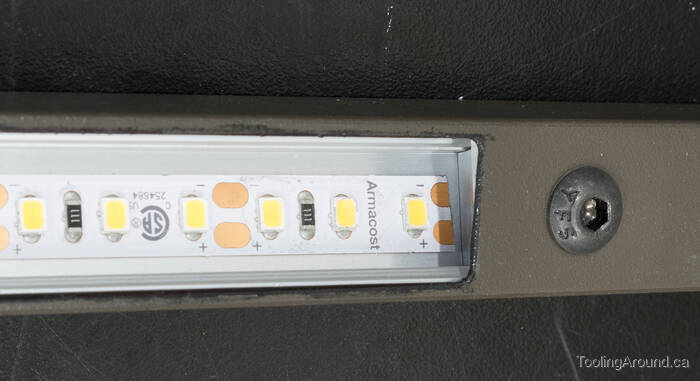
Install the button head screws to hold it in place.
At the top edge of this photo, you may notice that the diffuser has been installed, but it's not tilted within the top tube. That's because this photo was taken before the side tubes had been shortened to make the Mark 2 version of the lamp. You may notice this in other photos, too.
And now install the side tube.
Next is the bottom left joiner.
Add the bottom tube.
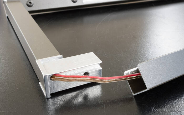
Nice and tidy with the bottom tube.
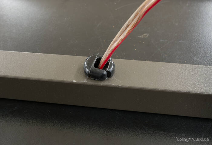
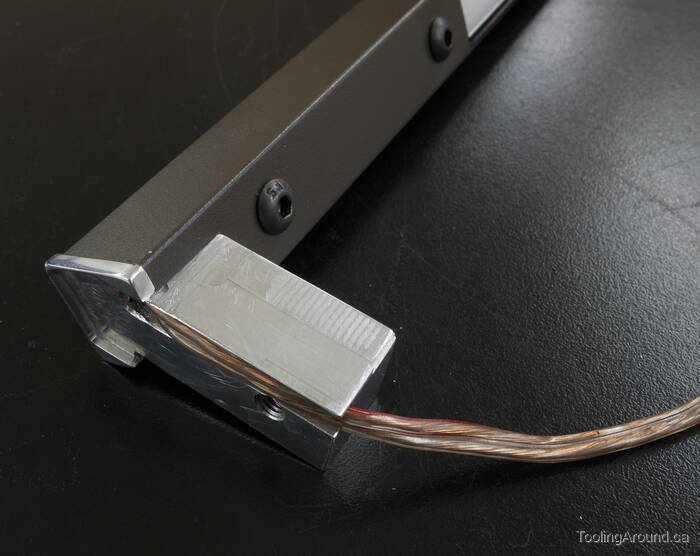
Restrain and protect the wire where it comes out of the bottom tube.
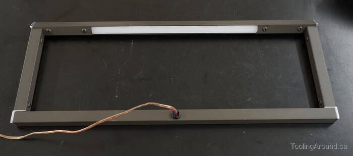
With the right tube and joiners installed, it's complete.
Installation
Installation was a two-part process. First, to fit the lamp to the pulpit, I brought the easel home, where I had my tools. Then I took it to the church and installed the power supply and dimmer control.
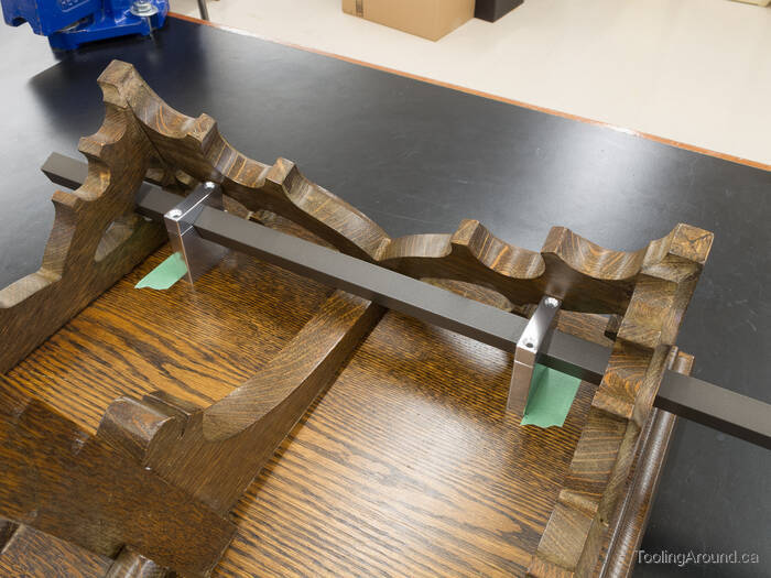
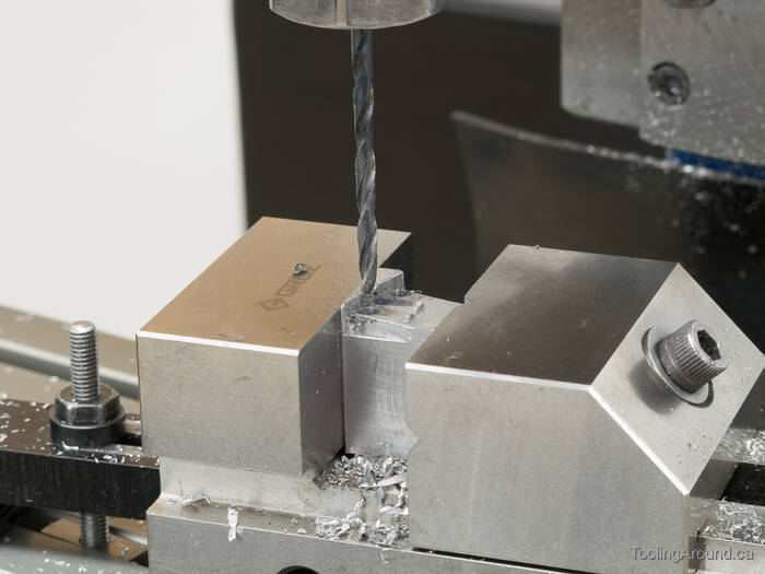
Preparing to drill screw holes for the supports, I used a couple of bits of masking tape to mark the locations of the supports.
This is when I encountered the first real problem on this project. The supports really need to be installed a bit forward of where they are, so the tube will be centred in the spaces in the carved sides. However, they're bumping up against the front apron and can't move further forward.
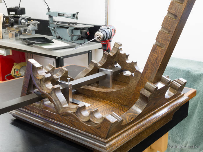
I wondered about making new supports, but if you look at the screw on the left support, you will see that its head will just nicely clear the apron. Even if I made new supports or modified these, it would not be possible to drive that screw into place.
In the background, you can see the long drill bit that I used to get to the places where I needed the holes.
So, the lamp can be installed, but the bottom tube isn't quite centred where it's meant to be. Ah, well, it's fine.
This is just a test fit, but it's looking pretty good.
Although they're visible from this angle, the supports will barely be seen on the pulpit.
The next step was to undo two button head screws and slide the right tube and its joiners out of the top and bottom tubes. After clamping the bottom tube in the supports, I could slide the joiners back in and fix them in place with the two screws.
It's as good as I could have hoped.
If you look closely, you can see the power cord dropping down out of sight to where it's connected to the dimmer control. There's enough slack in the cord to permit height adjustment of the easel.
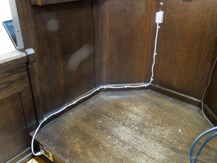
There's the power supply, with the cord fastened up to avoid foot traffic. The dimmer control is just above the power supply, where it's easy to reach.
And there's light at the business end.

Here's the drawing that I made to help me build this lamp.