 Tooling Around
Toyo Lathe – Handwheel
One of the many things that I have learned is that it is a good idea to cut threads by using a crank to turn the lathe spindle. This is contrary to industrial practice, where it is very important to produce work quickly and efficiently. However, on our little lathes, hand power is often preferable because it's the easiest way to achieve the desired combination of low speed, relatively high torque and precise control. Had I had known this many years ago when I first acquired this lathe, I would have avoided an exciting, not-to-be-repeated experience threading under power. No harm was done, but it was exciting!
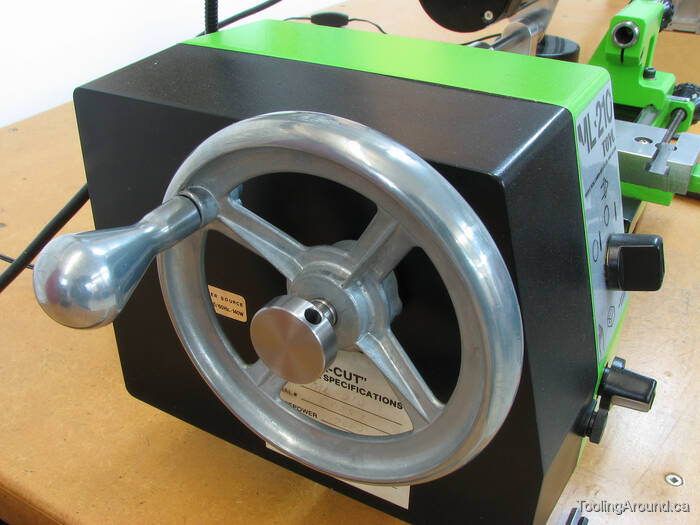
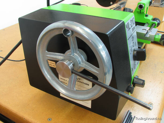
Rather than use a crank, I opted for a handwheel, simply because I came across what appeared to be a useful one, at a good price. On balance, I'm happy with it, although it offers less torque than a longer-handled solution would. (Maybe that's a good thing.) Although a knob is shown in this picture, when cutting threads, I just grip the rim of the handwheel. When returning the carriage for another pass, I use the knob because it's faster and easier.
Mandrels (Skip to "Drawbar".)
It made sense to adapt the handwheel to both the Toyo and Taig lathes, by making two mandrels. The only difference is the diameter of the long part of each mandrel, which fits the bore of each lathe's headstock spindle.
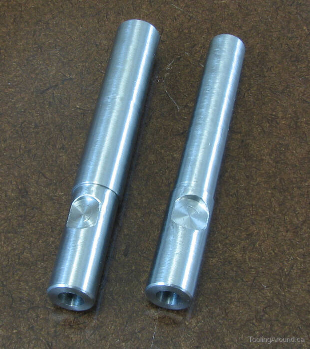
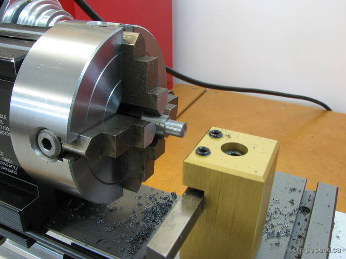
This photo shows the mandrels after turning the outside diameters. One end of each matches the handwheel bore and has a flat for the handwheel grub screw. Provision of a flat avoids raising a sharp, little edge when the grub screw is tightened. That edge would catch on the inside of the handwheel bore when it's time to pull it off the mandrel.
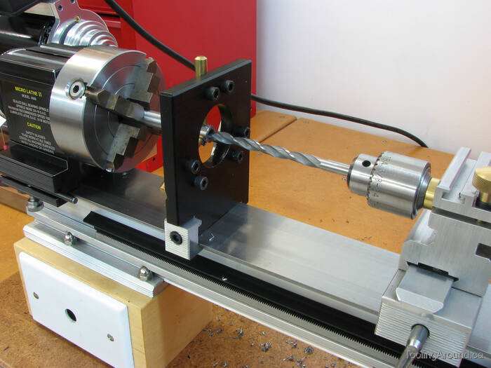
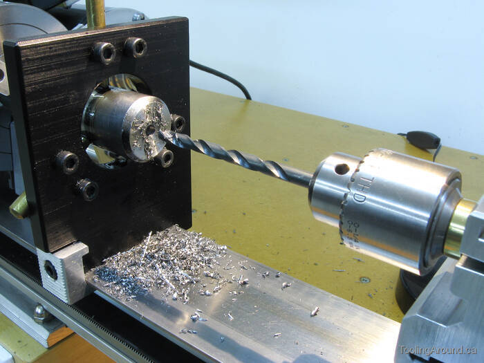
A hole was drilled the length of each mandrel, to clear the attaching screw.
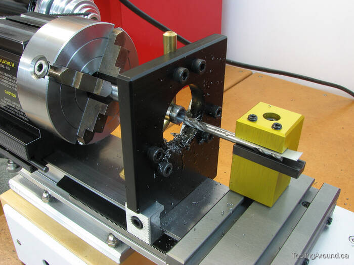
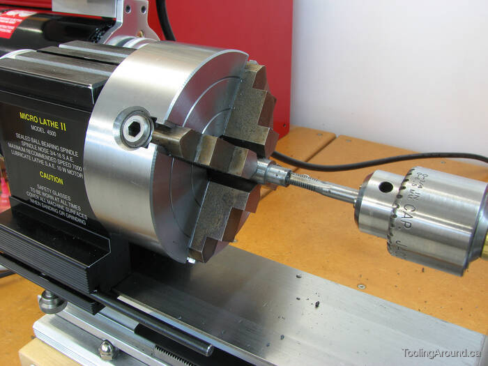
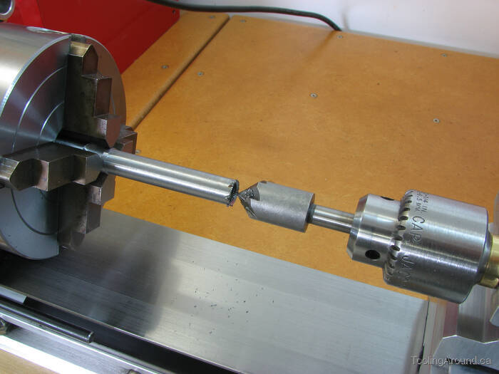
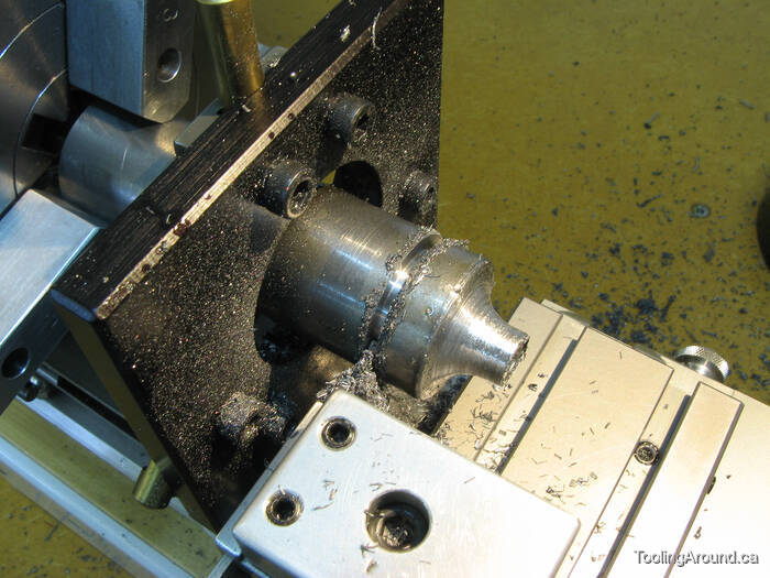
The end of each mandrel was bored to accept its nut. The “boring bar” is an end mill. One point is being used to make the cut. The tool was rotated to place the point at centre height.
It was a case of using what was available at the time. A small boring bar would have been preferable, but this actually worked very well.
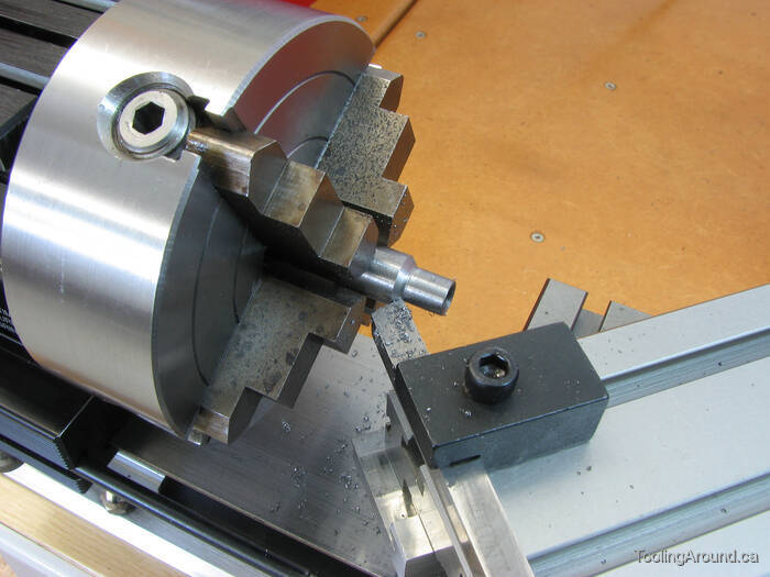
One end of each nut was reduced to fit the bore in its arbor.
Each nut was tapped for the screw. For this operation, it would have been handy to have a handwheel to turn the headstock mandrel.
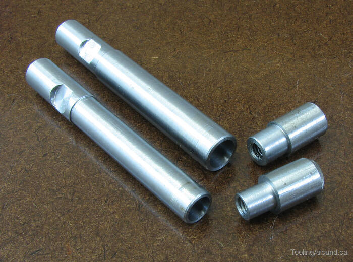
To recap, there are now two mandrels with matching nuts.
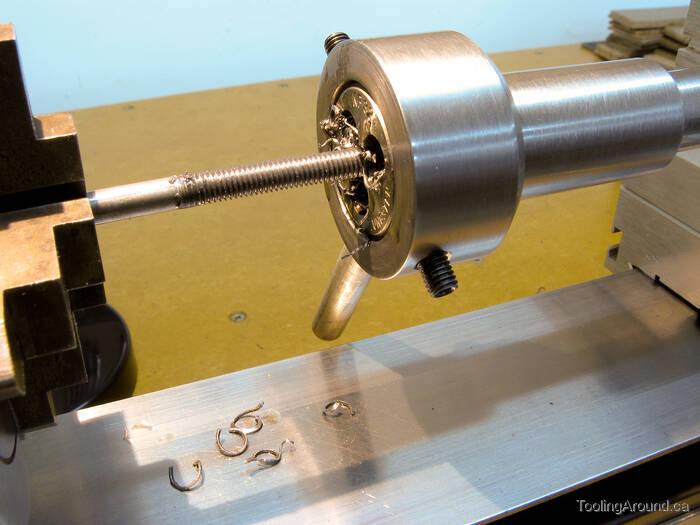
When you don't have a tailstock-mounted die holder, this is how you cut threads. Elsewhere on this site, you can see how I made my die holder.
I used a countersink to cut a taper on the inside of each mandrel.
Then I cut a matching taper on each nut.
I cut four slots in each mandrel, so the end can be forced to spread. A slot was cut almost through the side of each nut.
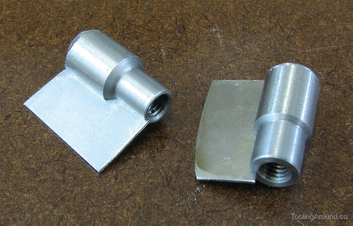
Over-sized tabs were fitted to both nuts and silver brazed in position. They were left over-sized because that made them easier to handle. After brazing, a tap was run through to clean up the threads.
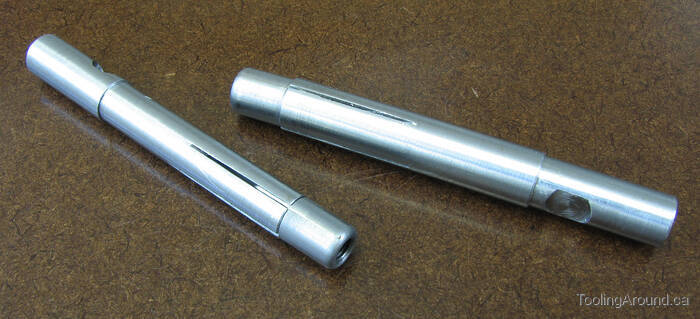
The tabs on the nuts were cut down to their final size. They keep the nut from turning when the screw is tightened.
Drawbar
A screw is required to pull the tapered plug into the split end of the mandrel. This tightening action will spread the mandrel's end, causing it to grip the inside of the headstock spindle by friction. At the other end, the screw needs some kind of handle, so it can be tightened, and a flat surface to bear on that end of the mandrel.
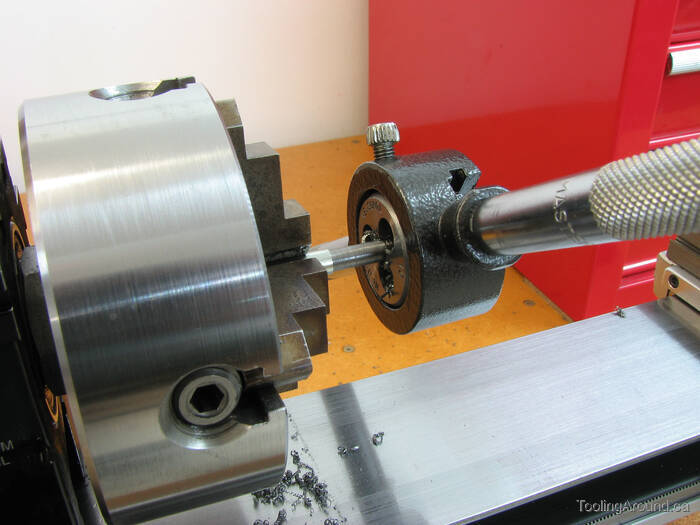
This photo shows the thread being cut on one end of the screw.
A hole was drilled in a short length of 12L14 steel round, to accept the unthreaded end of the screw. A short length of this piece of steel will be used to make a handle for the screw.
The curved part of the handle is decorative. I cut it using more or less coordinated movements of the carriage and cross slide handles. In the photo, a cut-off blade is being used to remove the handle from the piece of stock.
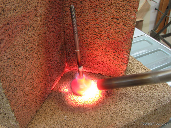
In this photo, you can see the silver brazing operation that joined the screw and its handle.
The two parts have been joined and the assembly has soaked in pickling solution. Then I scrubbed it with soap and water and cleaned off most of the residual dirt, preparatory to finishing it on the lathe. This approach meant that any slight misalignment of the parts would be corrected during the finishing of the handle
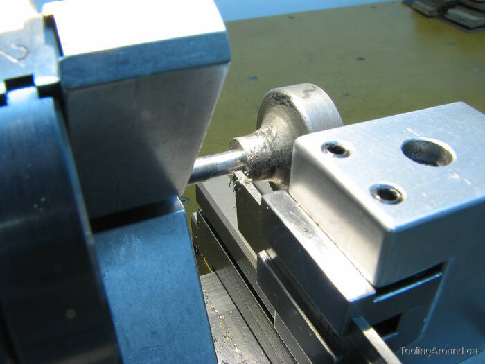
I used a parting tool to trim the brazing material from the joint and true the surface that would bear on the mandrel.
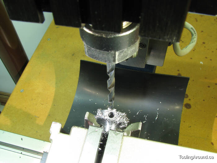
A hole was drilled in the handle, to accept a tommy bar. I sized it to accept one of the tommy bars that Taig provides to tighten the three-jaw chuck.
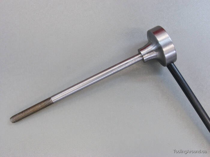
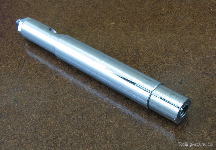
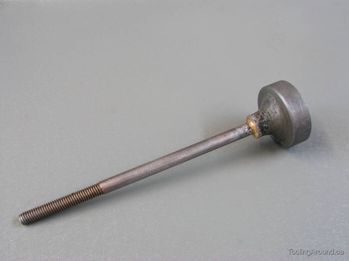
Here's the completed screw, with a tommy bar inserted in the hole.
Here's how it looked when it was finished.