 Tooling Around
Inside The Toyo Lathe
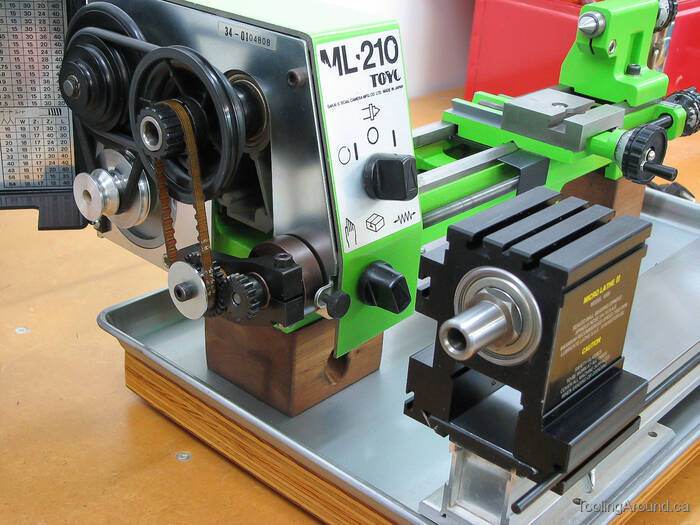
People frequently find this site when searching for information on Toyo lathes, so I decided to provide some pictures that show more detail.
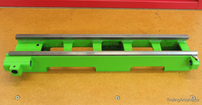
The lathe bed is made of fine cast iron, with hardened and ground ways. The protrusion on the left front houses the dog clutch for the lead screw. The one on the right front houses a lead screw bearing.
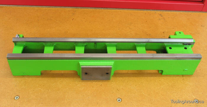
The rear view shows a mounting surface on the back of the lathe. This is where the column for the milling attachment is fastened to the lathe. (I do not have a milling attachment.)
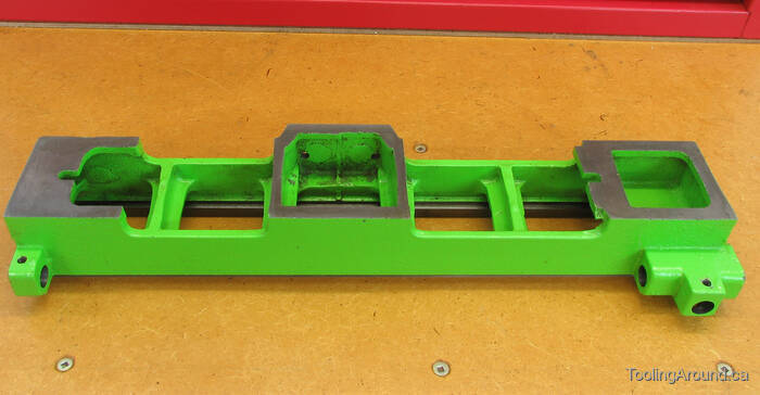
This view of the bottom shows the generous stiffening webs.
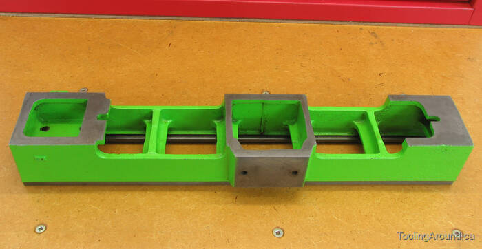
In this photo and the previous one, you can see a narrow, flat surface milled on the underside of each way for the full length of the ways. These flats are the bearing surfaces for a plate that holds the carriage to the ways, as described later on this page.
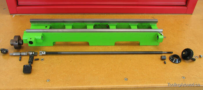
Here are the parts of the leadscrew, laid out approximately in their proper relationship.
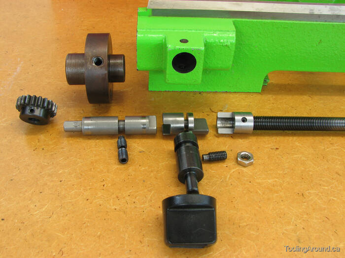
These parts drive the leadscrew. If you look at the leadscrew itself, you will see that a round, steel part is pinned to the end of the screw. This serves as a bearing for this end of the screw and is driven by the dog clutch. Approximately one half of the length of the bearing is milled away to make a flat that is engaged by the clutch. To the left of the bearing is the clutch. As you can see, one half of its diameter is likewise removed, to form a mating surface for the flat surface on the leadscrew bearing. The slot on the left end of the clutch engages the part immediately to its left, which is driven by the gear train.
So, how does it work? Starting at the left, the gear is mounted to the steel piece with the groove around its centre. This piece is slid into the bronze bearing shown just above it. The pair of grub screws are threaded into the hole in the bearing. If you look closely, you can see that the tip of the upper grub screw has been turned down, so it can engage the groove in the rotating piece. The second grub screw is turned down to jam against the first one. The net result of this is that the part will rotate freely inside the bearing and the first grub screw's tip will locate it laterally to keep it in the bearing. The short end of the bearing is inserted into a hole (not shown) in the left side of the projection on the lathe bed, where it is held in place by a SHCS, not shown in this photo.
Next, the clutch is inserted in the right-hand end of the hole, next to the first piece. The clutch shaft (the black piece) is then inserted into the front of the projection on the bed. If you look closely, you can just see a pin protruding from the end of the clutch shaft. This pin is located near the outer edge of the clutch shaft and engages the groove in the clutch. The grub screw is threaded into the projection on the bed, from below, directly opposite the hole that is visible in the top of the projection. The end of the grub screw slips into the groove in the clutch, to keep it in place while allowing it to rotate, and the lock nut secures the grub screw in position. Finally, the knob is attached to the end of the clutch shaft. Now it's evident that turning the knob to rotate the clutch shaft (and its pin) counter clockwise will move the clutch to the left, engaging it with the part that is driven via the gear. Moving the knob clockwise will move the clutch to the right, disengaging the drive.
The leadscrew, of course, is always engaged with the clutch, as the flat surfaces are long enough to allow the clutch to slide left and right without ever disengaging from the leadscrew.
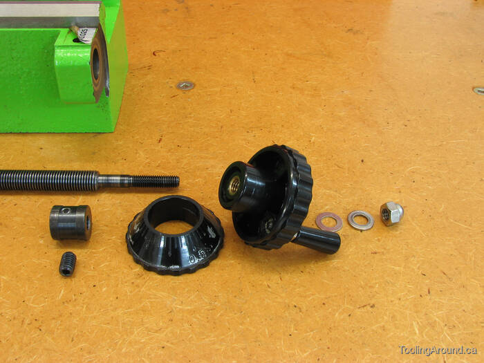
At the other end, we have a handwheel. The steel bearing is held in the protrusion on the casting by the grub screw, which is inserted from beneath the protrusion. This bearing also holds the leadscrew in position, laterally. The handwheel threads onto the end of the leadscrew and the acorn nut serves as a jam nut to lock it in place.
Incidentally, you can see the challenge of reading the calibrations on the resettable cone. One day, I shall make new ones.
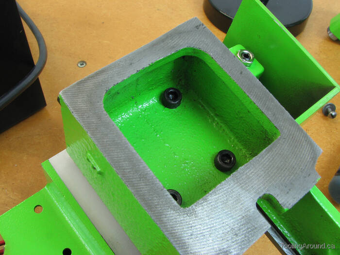
The aluminum headstock casting is attached to the bed by four socket head cap screws.
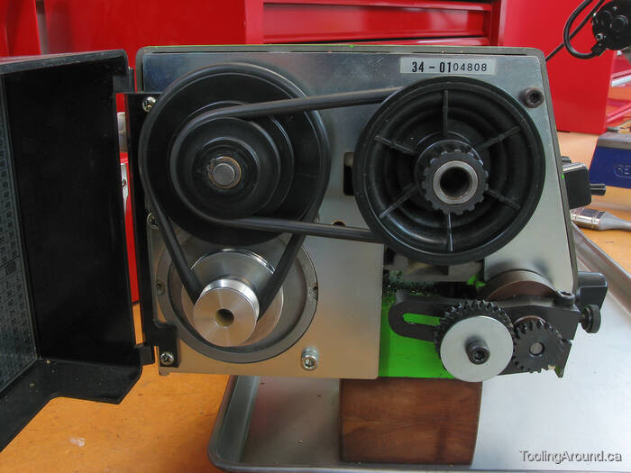
The motor is at the bottom left in this photo. Drive is by O-rings, to the intermediate pulley above the motor and then to the spindle.
The toothed gear on the end of the spindle is for a toothed belt that engages another toothed gear that is out of sight behind the large washer. This carries the drive to the leadscrew via whatever gears you care to install on the banjo. I mostly use this for threading and otherwise don't use the toothed belt. This saves wear on the components and besides, it's quieter.
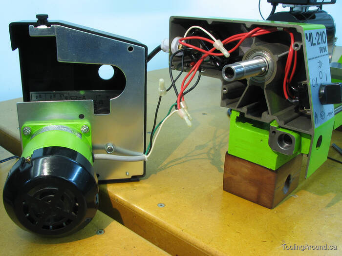
Here's the general arrangement of the motor and drive assembly and the wiring inside the headstock.
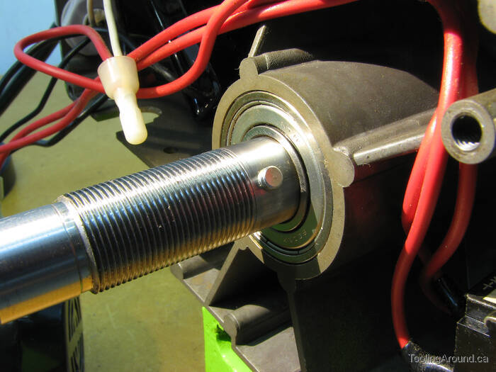
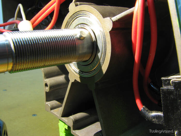
Here's the threaded end of the spindle. The pin engages the black collar shown in the next photo.
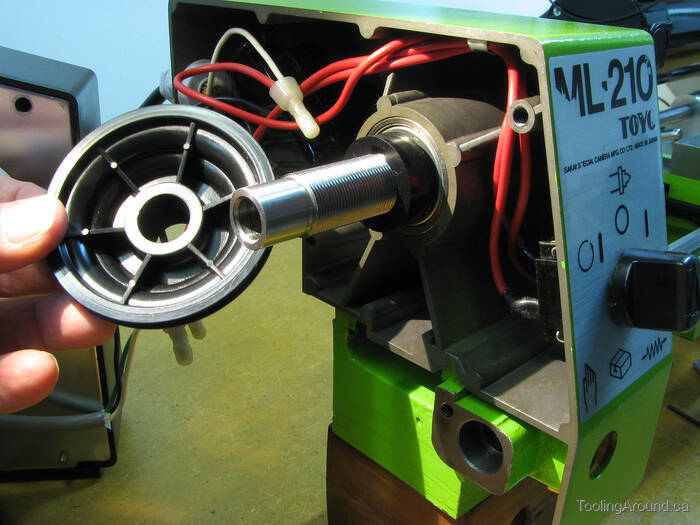
A black collar is on the spindle, with its slot over the pin shown in the previous photo. The collar diameter is smaller at one end, so it just presses against the inner cone of the bearing.
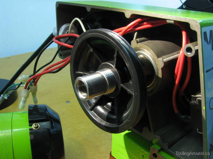
When the stepped pulley is threaded onto the spindle, it presses the collar against the bearing, to preload it.
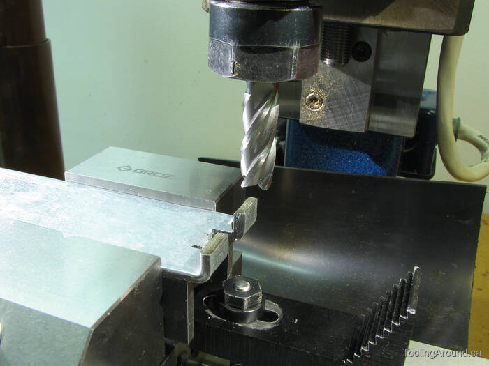
Okay, pause a moment while I make a wrench from a piece of flat bar from the scrap box.
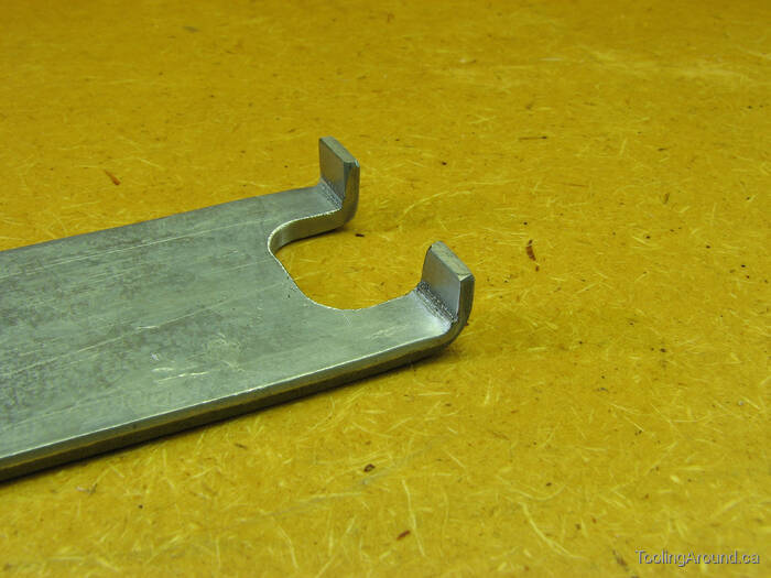
This wrench fits the slot in the locking nut shown in the next photo.
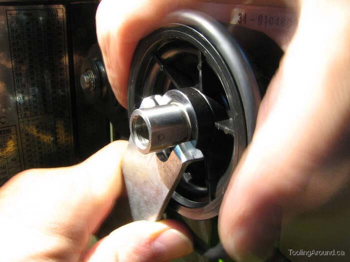
While holding the stepped pulley in place, the lock nut is jammed against the pulley to hold the preload position. Getting the preload right is a matter of trial and error. The spindle should spin without binding, but have no discernable end play.
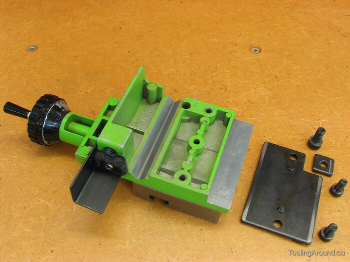
Here's the carriage. You can see the surfaces on the underside, where it slides on the ways. Also note the shield and the felt wipe that help keep the leadscrew clean.
To the right is the plate that holds the carriage against the ways. The wear marks show where it contacts the underside of the ways. It's pulled up snug by the two shorter socket head cap screws. It's kept from pulling too tight by the two grub screws the hold the plate off from the underside of the carriage. Careful adjustment of these four screws ensures easy movement of the carriage with no play.
The other SHCS and square washer are the carriage lock.
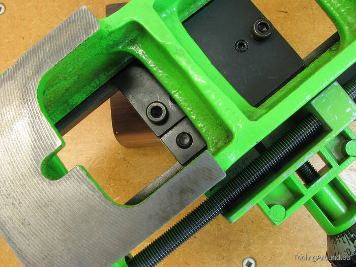
Here's the installed carriage, with the adjustment screws and the carriage lock screw and washer in place.
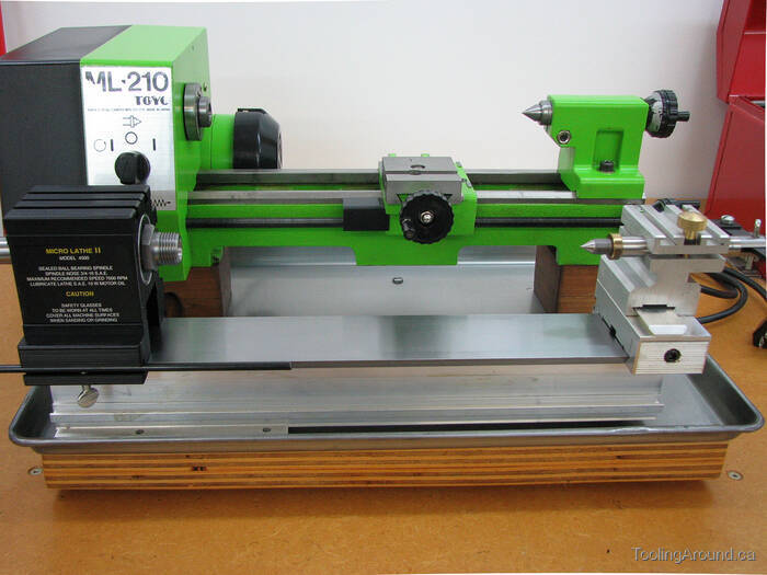
If you're familiar with the Taig lathe, this photograph will help you appreciate the size of the the Toyo ML-210 lathe.
This view of the Toyo and Taig headstocks illustrates some major differences.
- Although both headstocks are made of an aluminum alloy, the Toyo headstock is more complex and includes provision for the motor and its power switch. The Toyo headstock is a casting, whereas the Taig headstock is an extrusion.
- This Toyo is equipped for thread cutting via a toothed belt and change gears.
- The Toyo uses O-rings to connect the motor to the spindle, whereas the Taig uses a belt.
- The Toyo carriage is traversed via a leadscrew, whereas the Taig uses a rack and pinion.
Although the designs are very different, both are well-suited to the task.