 Tooling Around
Part 4 – Split Cotter & Rear Pedestal
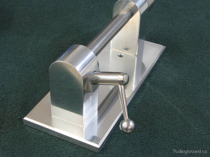
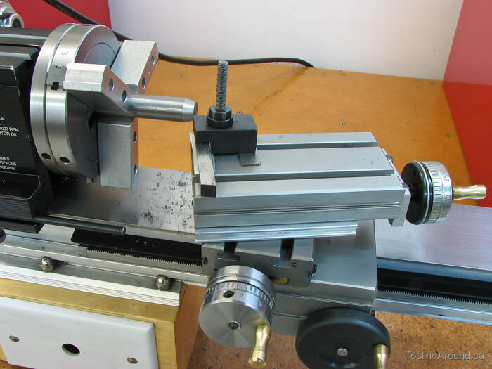
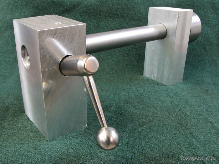
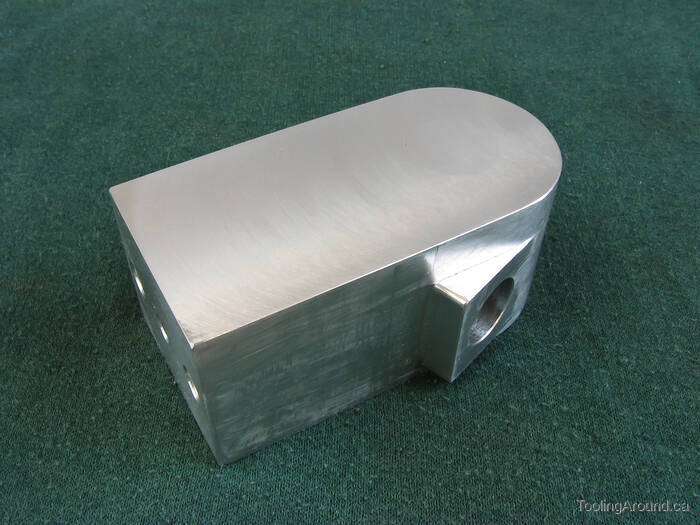
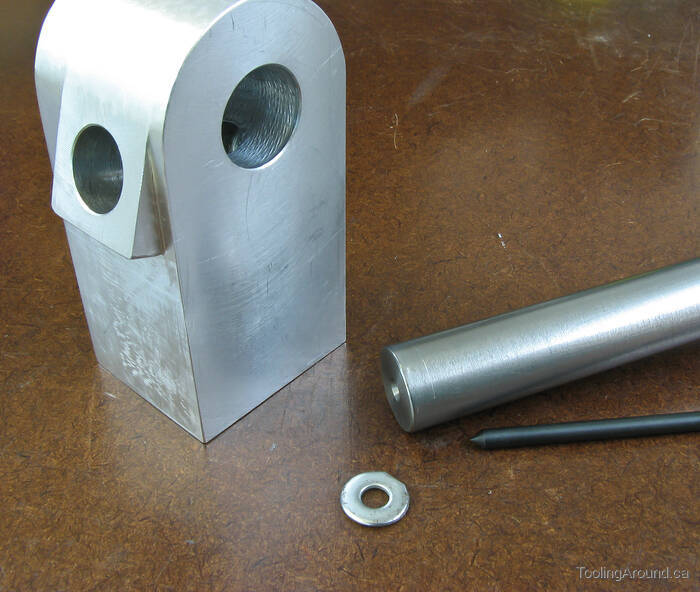
This photo shows three of the things I wanted to attempt in this project. Well, you can only actually see one of them, but they're all there. The one you can see is the ball handle, a nice touch, I think. It's used to tighten a split cotter, which you can't see. The third is the blind hole in the pedestal. Since you can't see it, either, it appears to have turned out OK.
Split Cotter (Skip to "Rear Pedestal".)
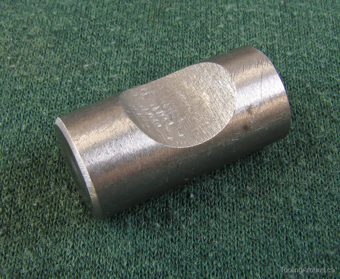
You may remember seeing this part at the end of the page about boring the pedestals. This is cut off the end of the rod shown in that picture. Since it was cut as part of the boring operation, it is known to match the diameter of the motor mount shaft, given that the bored hole matches the shaft.
The split cotter was, well, split (i.e. cut in two) and here I'm tapping the half that will be the nut. The other half was clearance drilled for the screw that will tighten the cotter. I decided to use a 10-24 thread, instead of the usual 10-32, on the theory that the screw will need less turning to tighten.
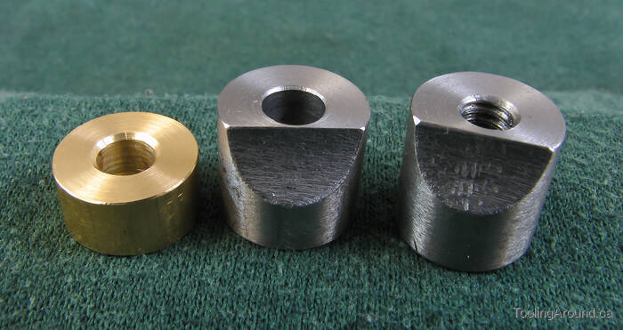
Here are the three parts that make up the split cotter. Well, two of them are the cotter and the brass piece is a washer. The washer is obviously much thicker than necessary, but it was made from a bit of scrap and I saw no reason to make it thinner.
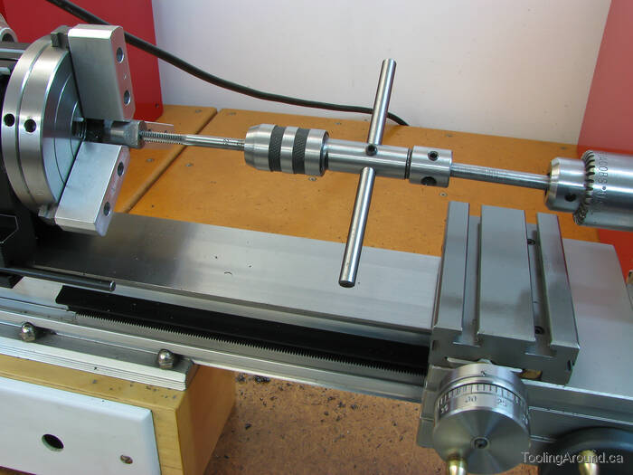
Another piece of the rod used to make the split cotter was used to make the screw. This photo shows a taper being cut on the end that will be visible.
After flipping the screw end for end in the chuck, I reduced the diameter and used a die to cut the required thread.
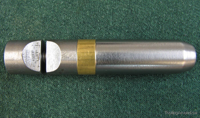
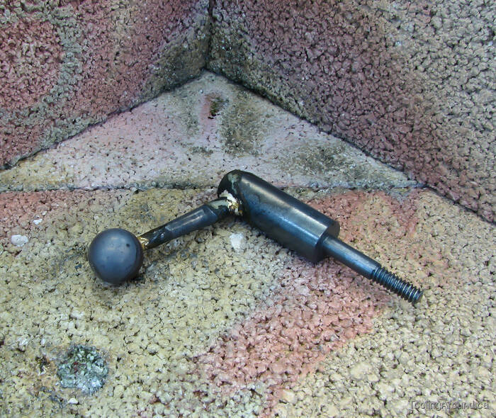
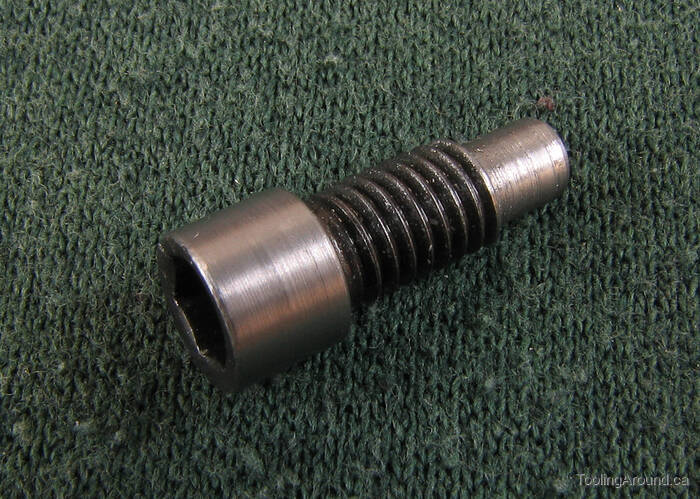
Here are the four parts, assembled to make the split cotter assembly. It would be difficult to tighten, however, so I made a ball handle.
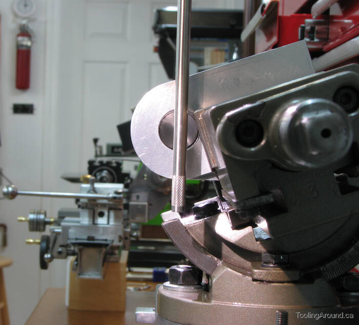
A short length of a small diameter suited to the ball has been turned and I'm about to turn a taper. There's nothing magic about the proportions. I just chose what I thought was pleasant to see.
You can read about setting a taper here.
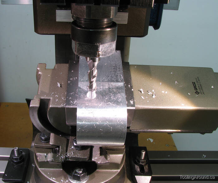
To attach the handle to the screw, I first used an end mill to make a flat. This served two purposes. First, it helped keep the drill bits from wandering. Second, it provided a good mating surface for the handle. After centre drilling, I enlarged the hole to the desired diameter.
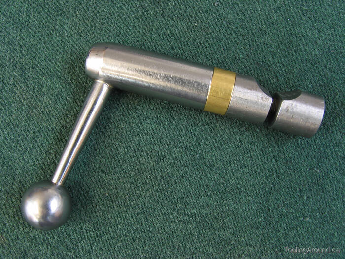
Here's how the handle looked as it cooled after the screw, handle and ball were silver brazed together.
The ball is one of the polish balls that I purchased from someone in Florida. I don't recall his name, but I found him on eBay. Polish balls are not ball bearings. They're made of unhardened steel and are used, I presume, in tumblers for polishing.
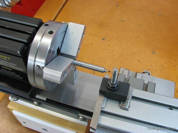
Here's the split cotter assembly, ready to use.
Here's the split cotter, being tested. The rather ugly bell-mouthed hole in the pedestal aside, it's actually coming together nicely.
Rear Pedestal (Skip to "Modifying The Shaft".)
The front pedestal is being milled to form a nice, rounded top. This is a straightforward operation.
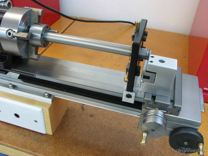
Yes, those are a couple of Taig lathe toolhoders being used as part of the work holding gear. They happen to be the correct size and it was convenient to place the threaded rod in the space normally used to hold a cutting tool.
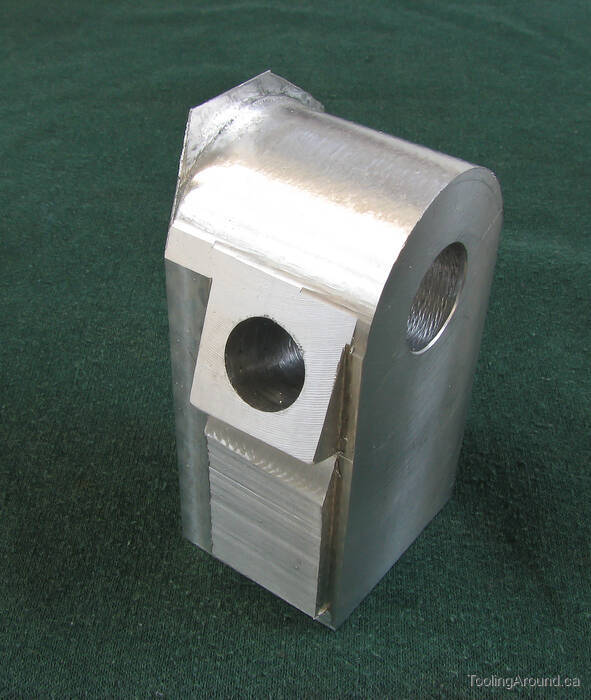
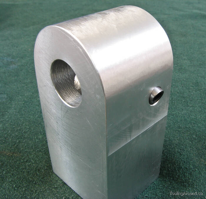
The rear pedestal is a little trickier than the front one, because of the projection that I want to leave where the split cotter screw enters the pedestal.
The pedestal is held in the vise, which has been tilted 25° and a flycutter is being use to face the projection down until it can form a fair curve with the top of the rear pedestal.
You may recall my use of a tilting vise in an earlier setup in this project. Between then and this step, I had purchased a three-way tilting vise, so this setup is much better than the previous one.
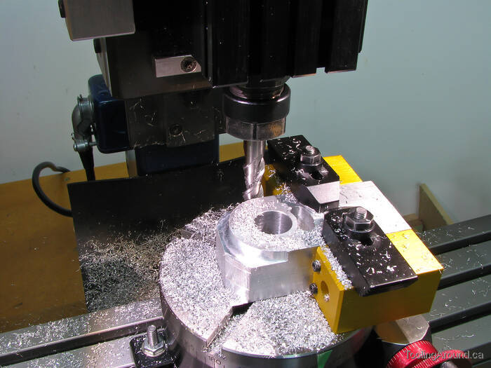
The rear pedestal is being centred on the rotary table so the top can be machined to a nice curve.
In this photo, you can see how the top has been shaped. It's still looking rough, but it's getting there.
There's a remnant of the pedestal that was not removed when shaping the rounded top. That's because the workpiece was clamped directly to the rotary table, so I had to cut close to the table, but not into it. This flange was easily removed by filing.
If you look at the projecting part with the hole in it, you can see that, while I had it set up for fly cutting (in an earlier step), I also used an endmill to trim away the edge at 90° to the flycut surface.
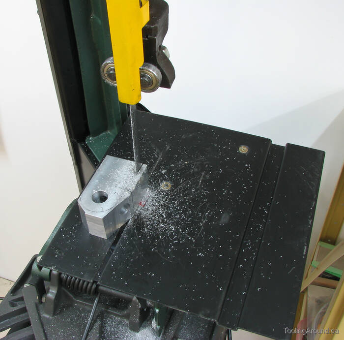
Back to the mill to cut away the front side of the pedestal, all but the projecting portion.
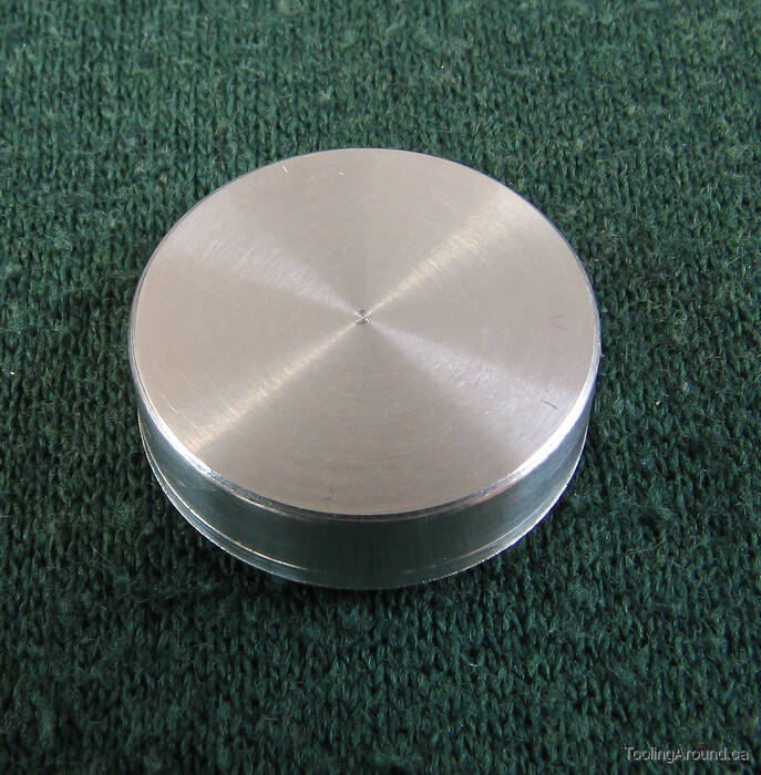
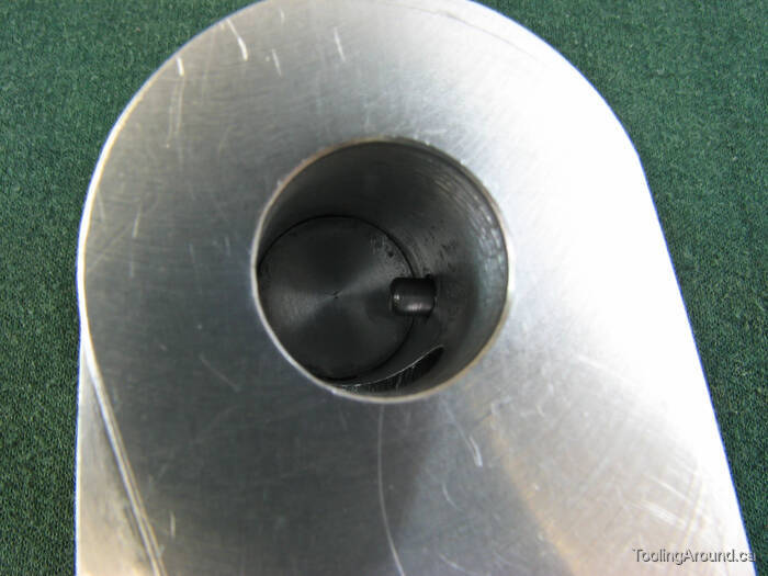
OK, remember that blind hole that I wanted, the one that goes all the way through the pedestal? I turned a button to plug the hole. It's a tight press fit, so I pressed it tightly into the hole. It's actually tapered slightly, so it tightens as it goes deeper into the hole.
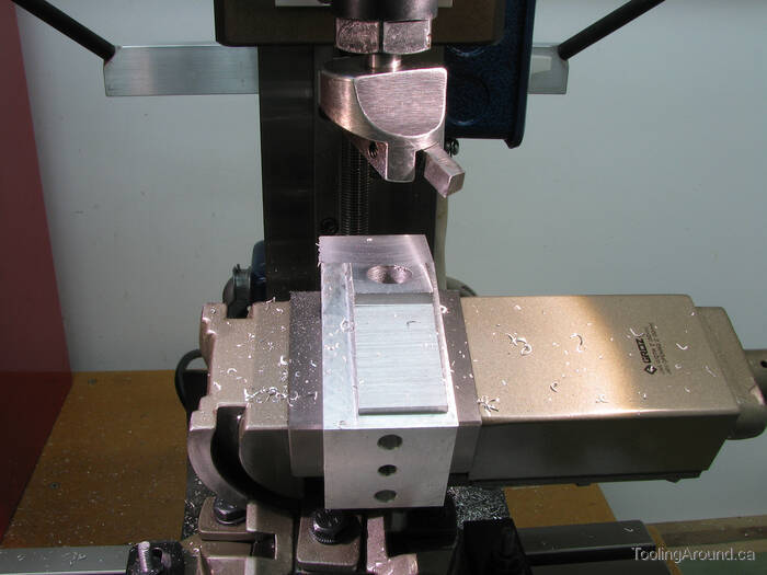
Now that the hole's plugged, with the plug still protruding a bit, I flycut the entire surface.
If you don't look too closely, you can hardly see the plugged hole. You can see it, however, and the reason is that the rod from which I cut the plug is not exactly the same grade of aluminum as the pedestal. After it's polished, it will pretty much disappear.
You can also see the result of a bit of careful filing to make a fair curve from the front of the pedestal and the projecting part of the pedestal to the curved top.
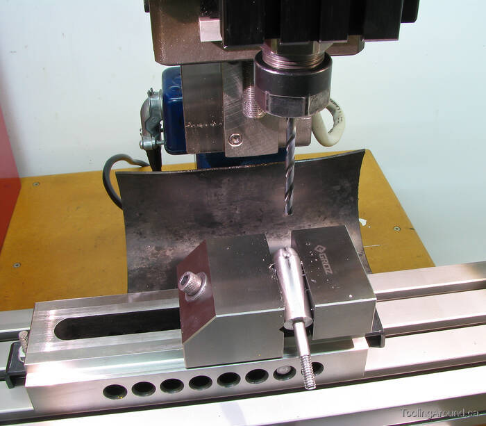
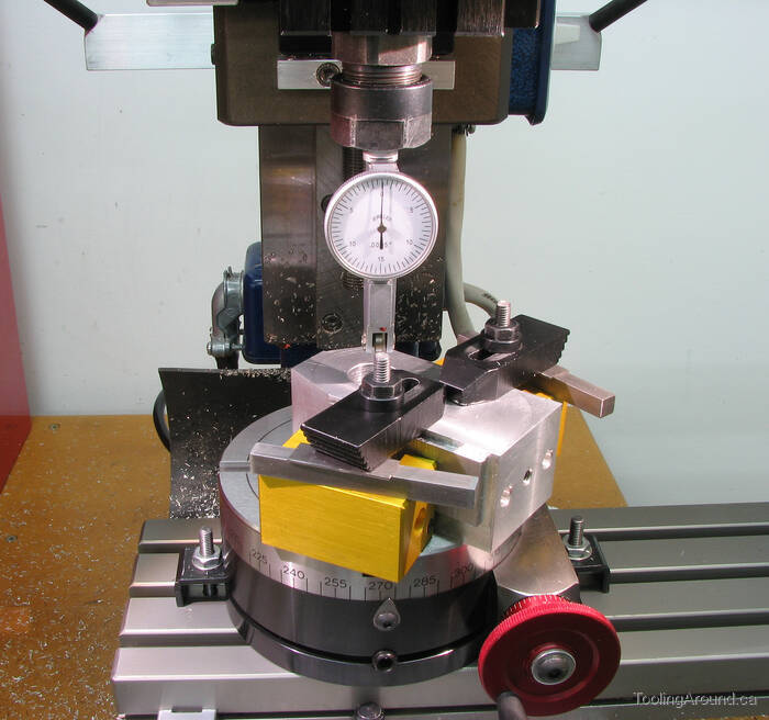
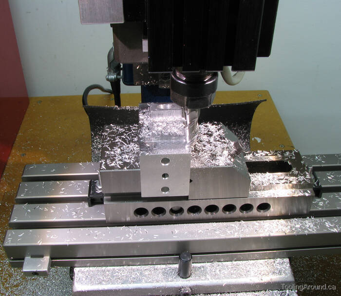
This next operation was not critical, so I lined it up “by eye”. The vise is tilted 20°. I mounted a piece of tubing in a collet in the mill and used it as a guide to centre the mill spindle over the hole. It didn't have to be precise.
After shifting the table to a suitable location, I drilled a hole for a retaining screw and then counterbored for the screw head.
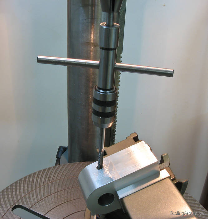
Using the greater work envelope of the drill press, I tapped the hole for the retaining screw.
By the way, there's a rod projecting from the top end of the tap handle. It's gripped loosely in the drill chuck, and is free to move while the chuck remains stationary. This is one way to keep a tap aligned correctly. The tap is not being turned under power, of course.
Here's the retaining screw. It's a SHCS with the head turned down, just to make it unobtrusive. The screw has been shortened and the tip turned down and rounded over.
Here's how the retaining screw looks from outside. It's tightened down against the bottom of the counterbore, so it won't vibrate loose.
And here's how the retaining screw looks, inside. Just the tip enters the shaft hole.
Modifying The Shaft
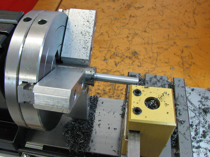
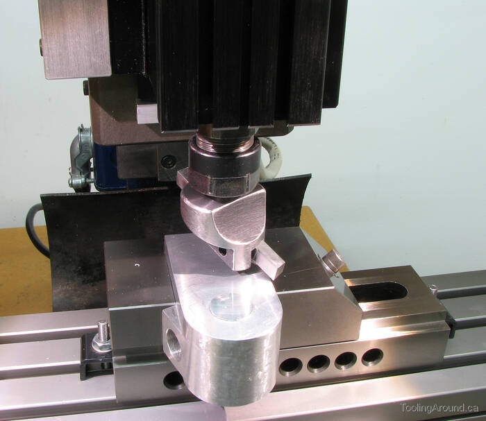
After removing the retaining screw, I inserted the shaft and put a transfer punch through the retaining screw hole. Pressing the sharp end of the punch against the shaft, I twisted the shaft to scratch it, marking the location of the retaining tool tip on the shaft.
Here's the business end of the transfer punch. You can see the faint scratch on the shaft.
The washer was in the hole, down against the plug, when the shaft was being marked. It served as a spacer to keep the end of the shaft clear of the plug. It is not included in the final assembly.
Back in the lathe and a groove is being cut in the shaft to make room for the retaining screw.
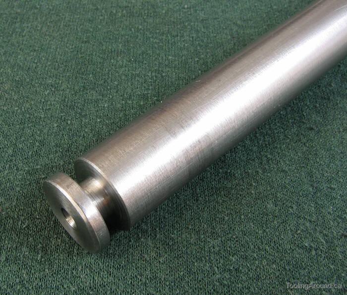
Here's the groove, ready to go. The whole point of this exercise to to make sure that the shaft doesn't work its way out of position in the pedestals.