 Tooling Around
Part 3 – Shaft & Front Pedestal
To recap, after the last page, the pedestals are now roughed out. The bottoms are faced and drilled for installation on the base. The rear sides are faced. The next thing I did was to make the shaft and finish the front pedestal.
After facing one end of a 1″ length of 1.5″ 12L14 steel bar, I drilled and then bored a hole for a sliding fit on the shaft.
The motor mounting plate will be attached to this hub.
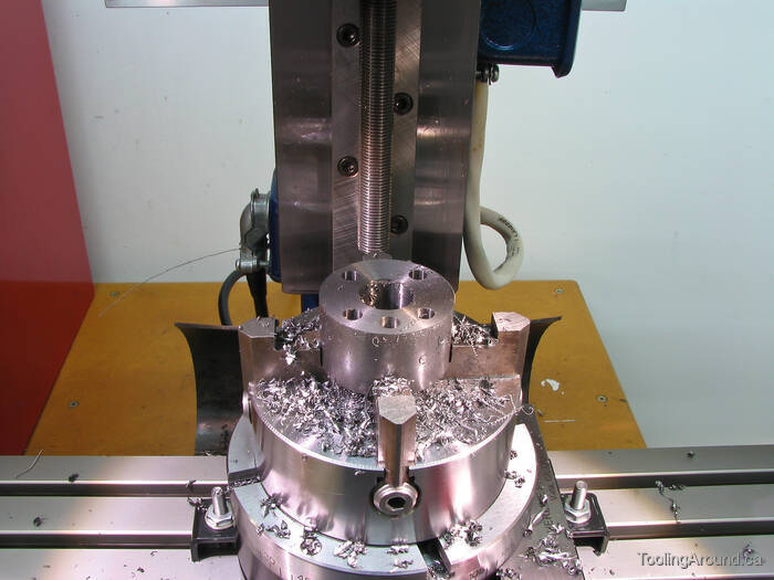
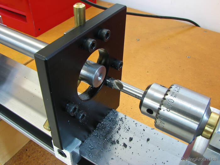
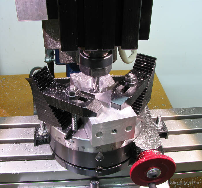
After centring the hub under the mill spindle, as described on the Centring A Rotary Table page, I moved the table by the desired radius and drilled four holes at 90° intervals, and a fifth hole 22.5° from one of them.
The first four holes will be tapped for mounting screws for the motor plate. The other hole will hold a dowel that will limit the movement of the motor.
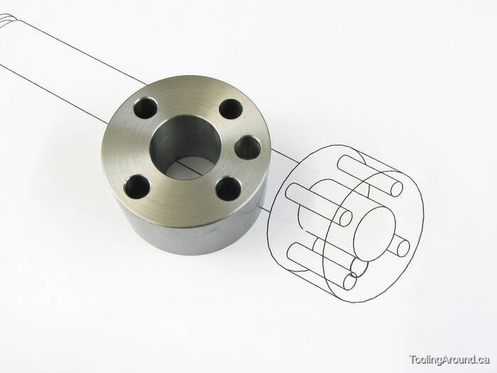
Here's the hub,looking remarkably like the drawing, always a good sign.
As a personal discipline, I've found it helpful to prepare a CAD drawing of some projects. If it's a really simple project, I may not do any drawing at all. However, where multiple components are involved, the act of drawing it helps me think it through before committing the idea to metal. This takes a bit of time, but has sometimes avoided significant errors when things don't come together as they should.

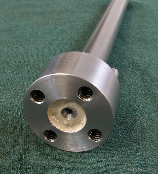
Here's another view of the hub, with the four mounting holes ready to accept 1/4-20 screws.
This photo shows the quality of the finish that can be obtained by boring. It's what I would have liked to have seen after boring the pedestals (described earlier).
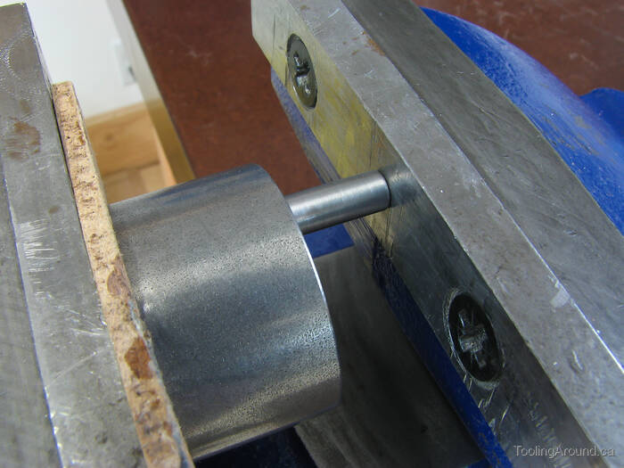
After turning a piece of steel rod to, well, a press fit, I used a vise to press the dowel into the hub.
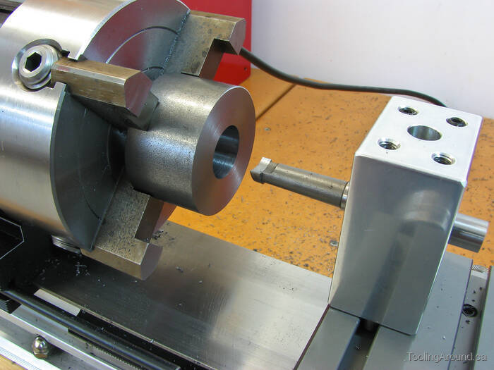
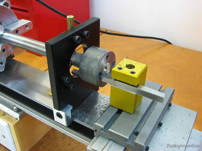
The shaft is supported by the steady rest, so I can centre drill the shaft. (Adjustment of the steady rest is described on the Adjusting A Steady Rest page.)
The reason for this operation is so I will have a support point later, when I true up the hub.
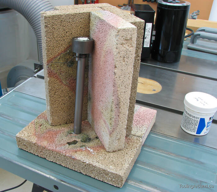
Here's the setup for silver brazing the hub to the shaft. (More information about silver brazing is available on the Silver Brazing page.)
Note that the hub is wired to the shaft, so it won't slide down. It's not a press fit, as there needs to be room for the brazing material to get into the joint, and the flux makes it a bit slippery.
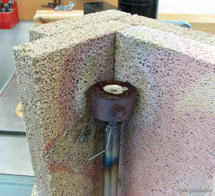
By the time I got my camera into position, the red glow was coming off the hub, but you can sort of see it in this photo. You can also see that, in my enthusiasm, I used way too much brazing material. Live and learn.
Back to the lathe for a facing cut. This ensured that the motor plate would seat properly on the hub.
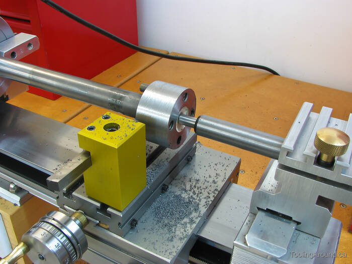
Here's the reason for the earlier centre drilling. A light cut trues the hub. Now, in use, it won't actually be spinning, so truing is really cosmetic, but there's no reason it shouldn't look good.
This end of the shaft is now finished. Work on the other end will wait until the rear pedestal is finished.
With nothing to restrain it when the split cotter is released, the motor would easily flop over, crashing onto the base or benchtop. So, this curved slot was cut in the side of the pedestal to accept the pin on the back of the hub. The slot is a bit wider than the pin's diameter, as we don't want it to rub on the sides of the slot.
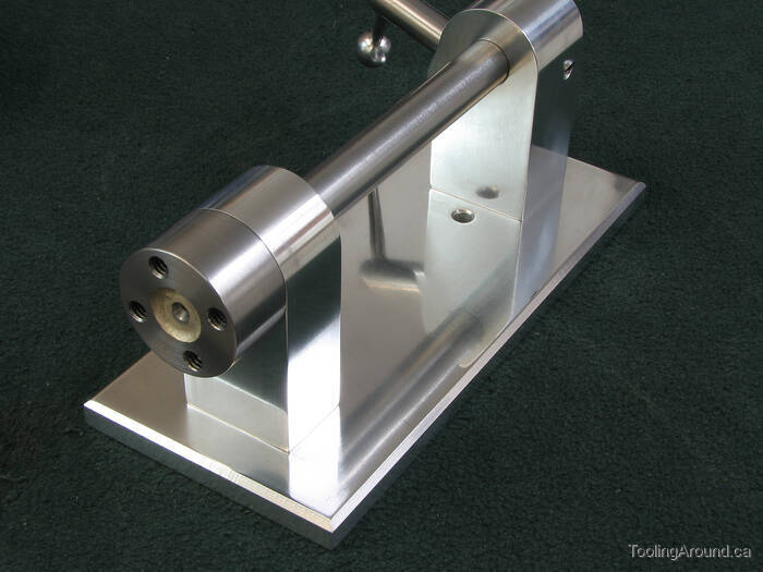
This design appeals to me because it's simple, strong and elegant. On the assembled stand, there's no external indication that it exists, but the motor doesn't flop over.
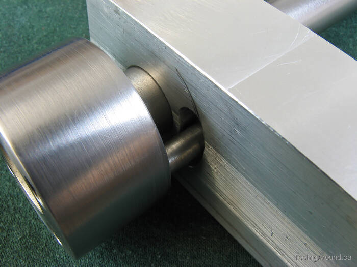
Here's how it works. When assembled, there will be no gap between the hub and the pedestal, of course.
The semicircular scratch on the pedestal was caused by a tiny burr on the hub, raised when cutting the threads for the mounting screws. Although I had checked the hub, apparently I hadn't looked closely enough. A touch with a small round file took care of the problem. Fortunately, the pedestal was still unfinished, so the scratch was removed during subsequent operations. (It wouldn't have shown, anyway.)