 Tooling Around
Taig Lathe – Cut-off Blade Holder
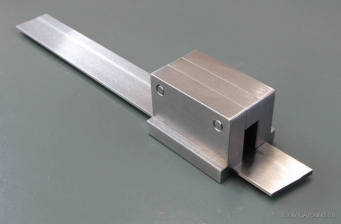
This is a cut-off blade holder designed to hold a 1/2″ HSS “P” type cut-off blade. The blade holds an edge well, as it is a steel alloy containing 5% cobalt.
Inspiration for this tool holder came from my friend Brian Finlayson, who is an excellent machinist. Mine consists of a steel blade holder, very similar to the one Brian made. The body of mine is made of aluminum, modelled after a typical Taig tool post, whereas Brian's is a rear mounted post made of steel and projecting off the back of the cross slide table.
Proponents of a rear-mounted (and upside down) cut-off blade have a valid argument to make. I chose to go a more conventional route, as I had other plans for the space behind the carriage.
Note that the blade is held horizontally. With some designs it is held at an angle, so the tip can be set to centre height by moving the blade fore and aft along the slope. With the design I'm using, the blade can be extended as required without changing the height of the cutting tip. Adjustment of the height can be accomplished in the conventional manner, by using shims. The “sloping” design requires the blade to be extended one specific distance in order to set the height correctly, which means that no fore-and-aft adjustment is possible. When I made mine, I carefully made the opening in the base to put the blade at centre height and it does not, in fact, require shims.
Blade Holder (Skip to "Tool Post".)
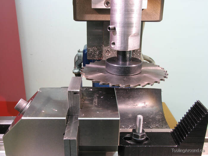
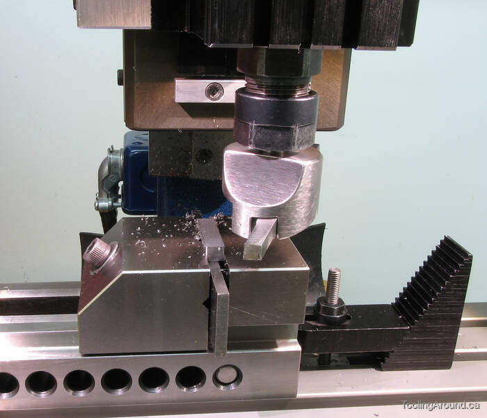
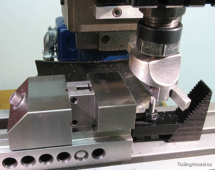
Using a 3″ x 1/16″ blade to cut a slot for the top of the cut-off blade. This produced a slot that is a match for the thickness of the wide part of the T-shaped blade.
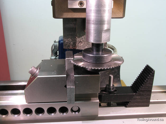
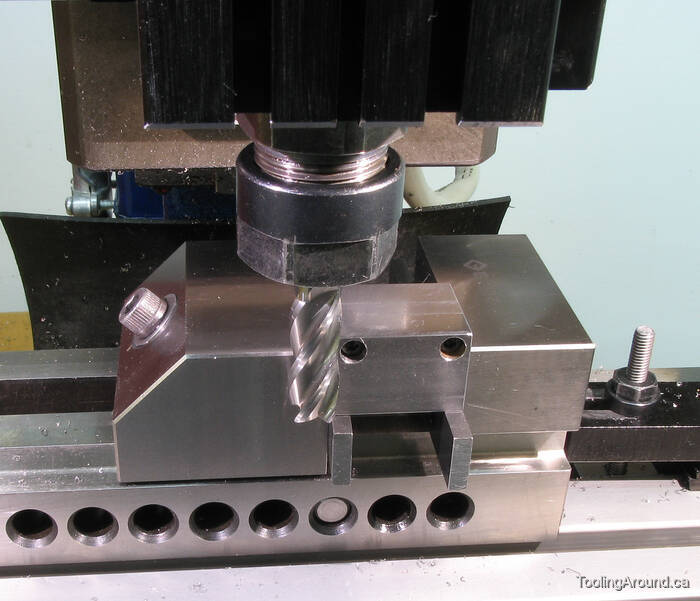
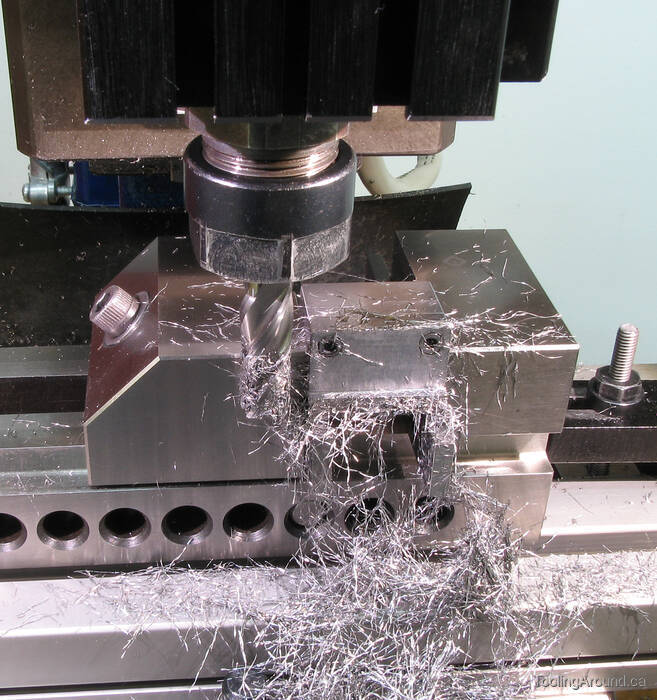
Using a 2-1/4″ x 0.032″ blade to cut a slot matching the thickness of the narrower bottom of the cut-off blade.
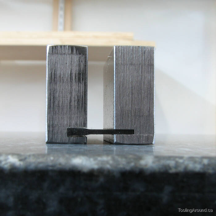
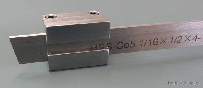
Here's the blade, nestled into the blade holder slots and sitting on a surface plate. As you can see, the blade is a close fit in the slots and the blade is parallel to the surface plate. The wide part of the blade tapers, providing the necessary relief on the sides when cutting, so it's just the widest part of the blade that is held closely in its slot.
The top and bottom parts of the blade holder are held apart by a spacer. In this photo, the spacer is sitting on a parallel for the fly cutting operation that ensures that the top and bottom surfaces of the spacer are parallel and that the spacer is the correct thickness.
With the spacer in place, the blade looks to be aligned properly and the top and bottom parts of the blade holder are parallel.
Holes have been drilled, tapped and counter bored so the blade holder can be assembled, using 4-40 socket head cap screws. The blade holder is tilted a bit because the ends of the cap screws are sticking out the other side.
Note that the counter boring is pretty deep. The reason will be apparent in a later step.
No care was taken to prepare the “back side” of the blade holder parts. It was easier to defer that work until the assembly was together and they could all be fly cut at the same time.
Similar to the back, both ends of the blade holder were fly cut.
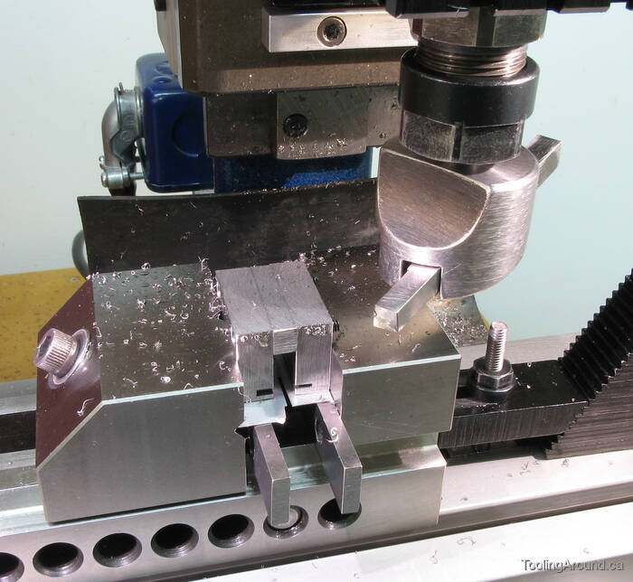
This photo shows why the SHCS holes were counterbored so deep. Now we have room to reduce the width of the blade holder without also removing the screw heads.
This is about as far as I went on this side of the blade holder. As you can see, I just grazed the screw heads (deliberately).
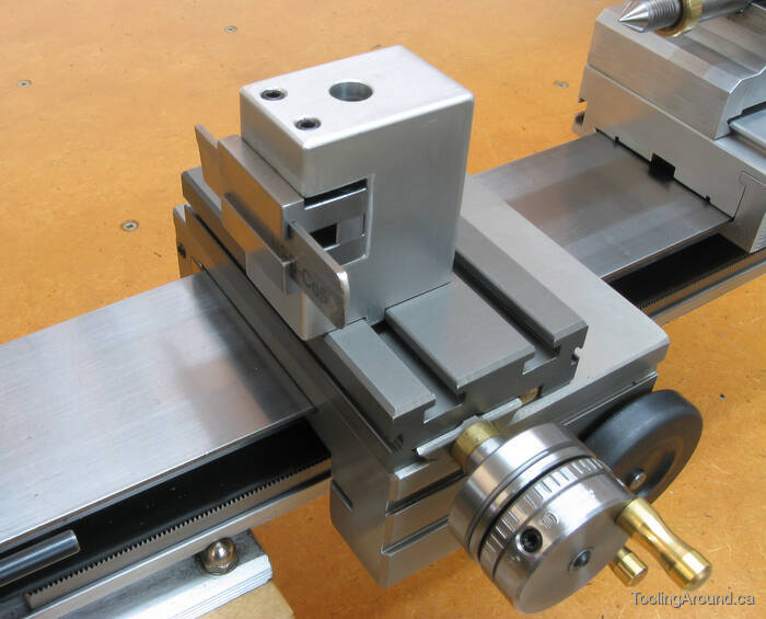
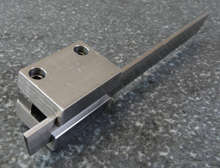
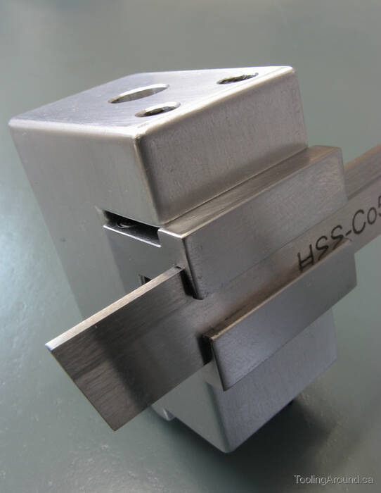
The cut-off blade holder is complete and ready to use.
At 4-1/2″ in length, the cut-off blade is clearly too long to use on such a small lathe. As you can see in the photo at the top of this page, I cut it in two and now I have one that is just right and a spare.
The holder looks pretty good from the back, too.
Tool Post (Skip to "Finished Tool Holder".)
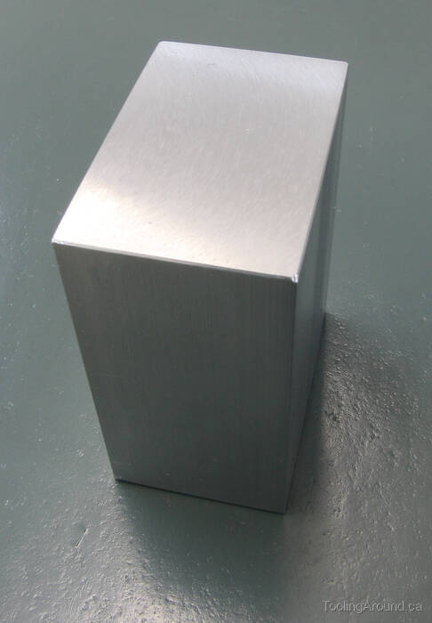
A short length of 1″×1.5″ aluminum bar, squared up and ready to be transformed into a tool post.
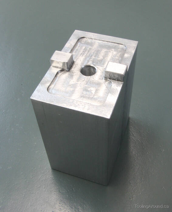
This is the bottom of the tool post. There are two things to notice in this photo. First, I've milled a recess so the post will sit on the cross slide just on its rim. This is consistent with the usual practice, which you can observe by looking at the underside of a Taig toolpost. Second, I've left two protruding tabs to align the toolpost with a cross slide T-slot. Since this is a parting tool holder, there's only one correct alignment and it's important that it be maintained. Otherwise, the cut-off blade will bind, with unpleasant results.
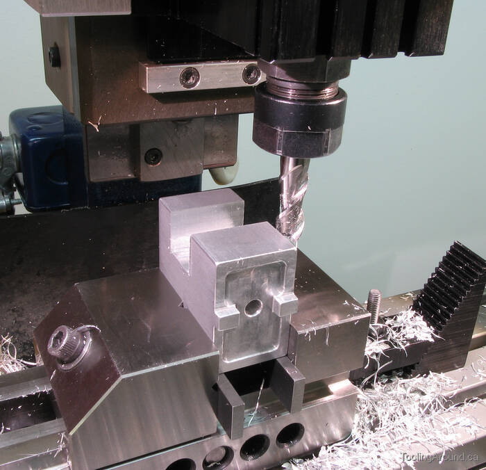
Here's how I milled the slot. It's really just like a stock tool post, except that the slot is extra wide and extra deep. I took care to mill the slot so the blade holder would put the blade at centre height.
Finished Tool Holder
Here's the completed blade holder.
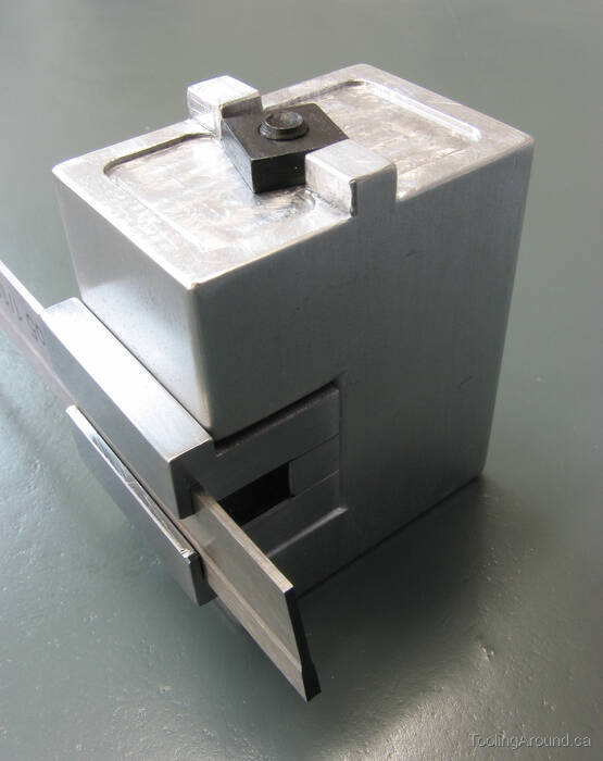
And here's the underside.