Tooling Around
Machinery Dolly
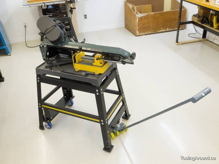
A number of years ago, we had a camper trailer and I was aware of trailer dollies, used to move trailers around “by hand” on a dealer's lot, for example. When I wanted a better way to move some machinery in my shop, I remembered trailer dollies and wondered if I could make something similar. However, I wanted something much smaller than a trailer dolly and could not think of how to make one. More correctly, I could think of several ways and all of them were too complicated.
Finally, the penny dropped when I remembered how a trailer's anti-sway bar is fixed to a trailer hitch, using a 1-1/4″ ball, as opposed to the typical 2″ ball on a trailer dolly. This was the key part that I needed and the rest of the design then fell into place in my mind. After purchasing a ball at a nearby trailer supply shop, all I had to do was figure out how to make the rest of the device. For the most part, I was able to find what I needed around the house and had to purchase very little.
In the photos on this page, you will see a mix of painted and unpainted parts, including a bit of black paint. My apologies, as I didn't make enough photographs during the initial construction and had to dismantle the dolly and make some additional ones for this page.
Handle (Skip to "Handle Mount".)
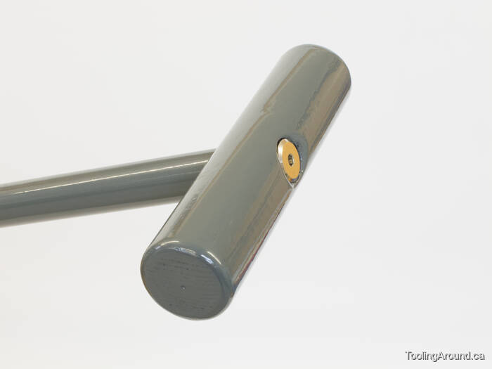
The handle is a piece of wooden dowel attached to a steel tube. The only interesting bit is how the two are attached to each other.
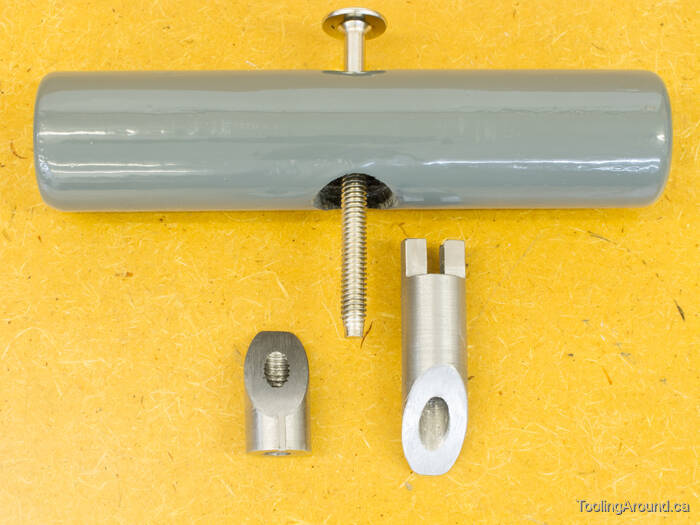
The secret is no secret at all, especially if you've ever seen how a bicycle handlebar stem used to be attached to the steering tube. The nut has a tapered side that slides up the tapered side of the matching piece, forcing them apart inside the steel tube and firmly fixing them in place.
To give you a sense of the dimensions, the bolt is 3-1/4″ long. The plug and nut were made from a piece of steel about 2-3/4″ long. The nut was cut off at a 30° angle, so it would slip nicely against the plug. The groove that you can see in the nut is just over 1/4″ long. The dowel's diameter is 1-3/8″ and it's 6″ long. There's nothing special about any of these measurements; they just felt about right.
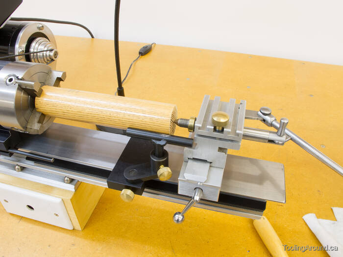
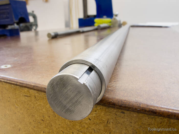
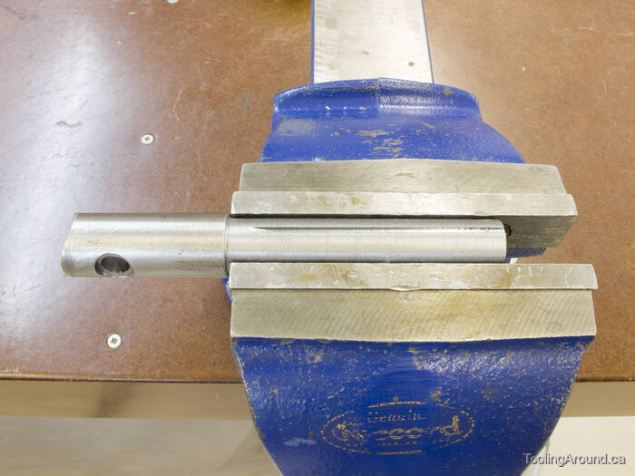
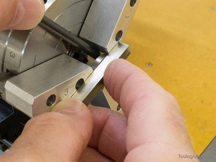
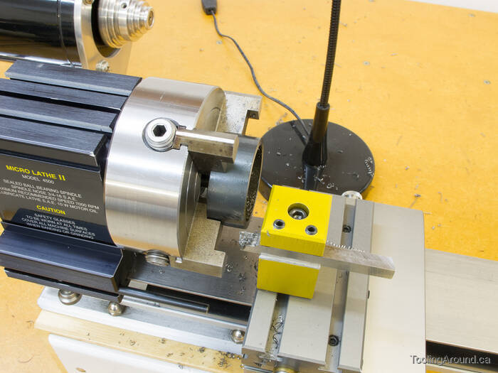
The dowel was salvaged from a worn-out snow shovel. (What can I say? I'm Canadian.) This is how I mounted it on the lathe to round off the edges.
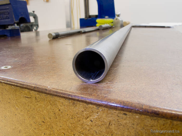
The steel tube is salvaged from an artificial Christmas tree and happened to be 3/4″ in diameter and 41″ long, which seemed like a suitable size. The only problem was the ridge from the welded joint, inside the tube. This ridge interfered with the fit of the attachment parts.
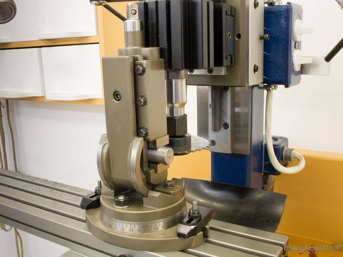
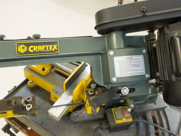
After turning a length of steel (salvaged from a damaged furnace blower) to the correct diameter, I mounted it in a tilting vise and used a slitting saw to cut a shallow groove.
Now it slid into the tube without interference.
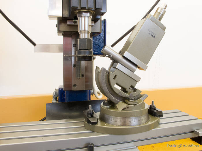
After drilling a hole the length of the plug, I used another tilting vise to hold it while I used the slitting saw to separate the plug and its nut. As you can guess from looking at this photo, the slitting saw didn't manage the full depth of cut, so I finished the last little bit with a hacksaw.
This is how the parts looked after I used a file to clean them up.
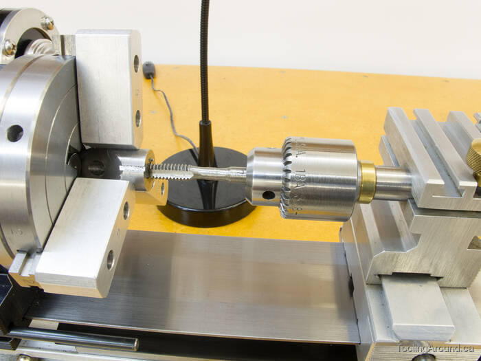
Having drilled the hole to the correct size with this next operation in mind, I cut 1/4″×24 tpi threads in the nut.
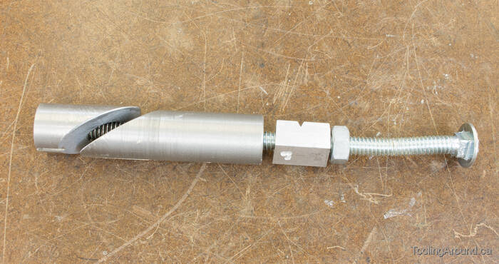
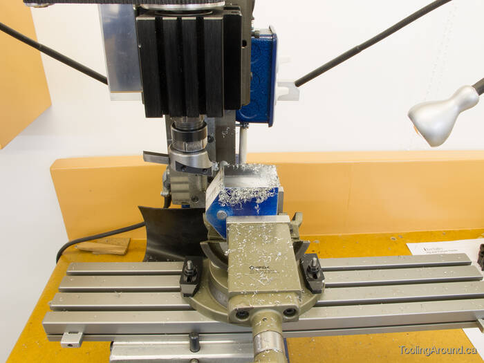
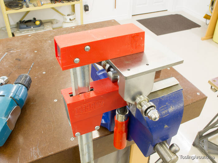
The next step was to shape the end of the plug and the tube to make a tenon that would fit a matching mortise in the wooden dowel. In my scrap box, I found a long carriage bolt that had definitely seen better days. From left to right, you can see the nut, the plug, a sacrificial scrap of aluminum and a hex nut. The plug was slipped into the end of the tube, so it was flush with the end of the tube, and the nut was tightened to fix it firmly in place. In effect, that end of the tube was now a solid steel bar.
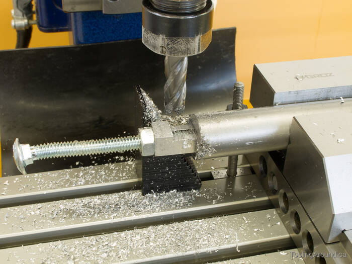
Back to the mill to cut one side of the tenon. In this photo, part of the sacrificial piece of aluminum has been removed and the cut has just started to progress into the plug and tube.
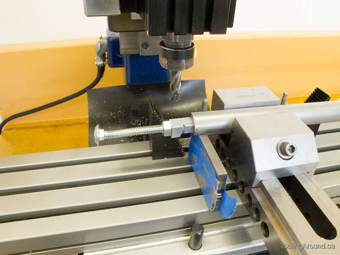
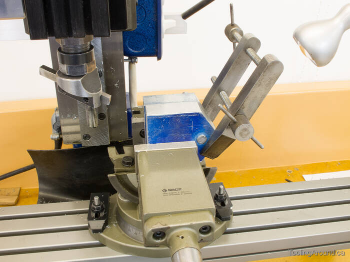
After cutting one side of the tenon, I rotated the tube to cut the other side. To make sure that this side would be parallel to the first one, I stacked up some lathe tool bits to make a surface on which to rest the first side. The blue masking tape held them in position until I tightened the vise, after which I removed them.
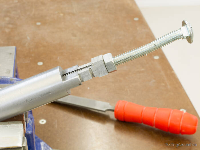
After using a file to clean off some burrs, this was the result.
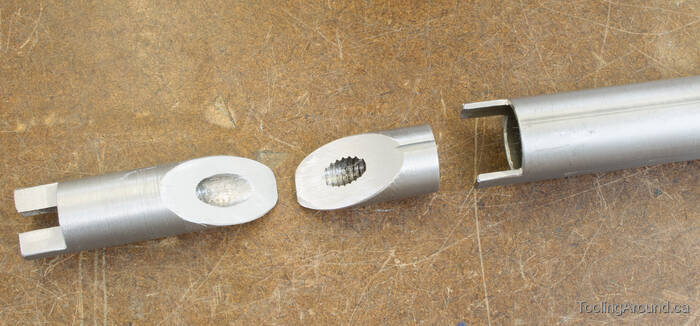
Here, you can clearly see the parts.
Now, I have a mortise to fit the tenon in the dowel. Please excuse the black paint—at one point during the construction, I painted the handle black but subsequently decided that grey would be a better choice.
This is how it slips together.
Handle Mount (Skip to "Vertical Frames".)
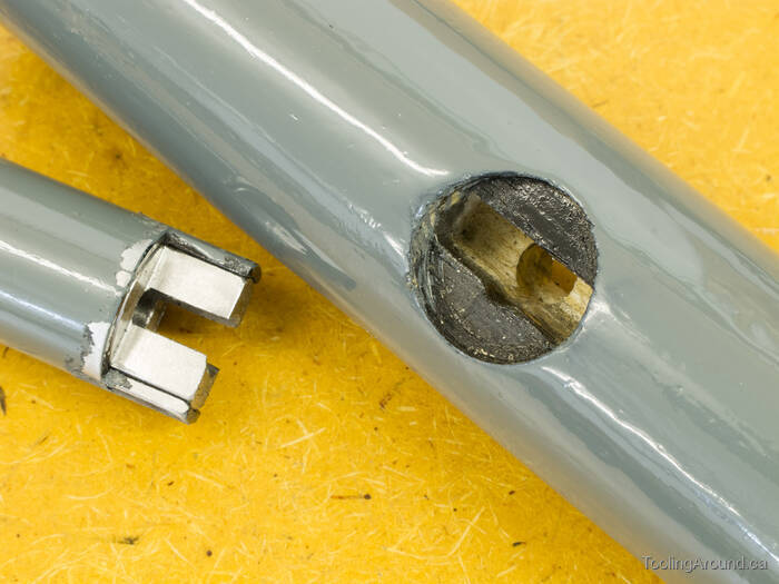
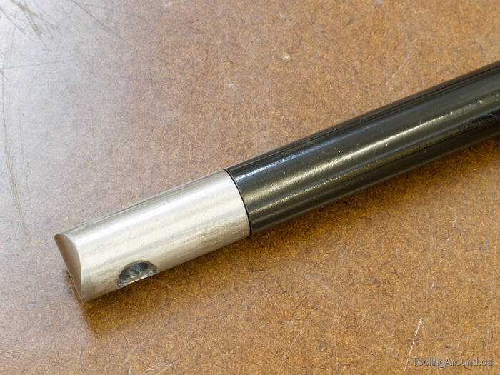
The other end of the handle is attached to the dolly's axle. The handle tube slips over what I'm calling “the handle mount”. Well, I suppose I needed to call it something, didn't I?
This photo shows the SHCS that goes through the side of the tube, to fix it to the handle mount.
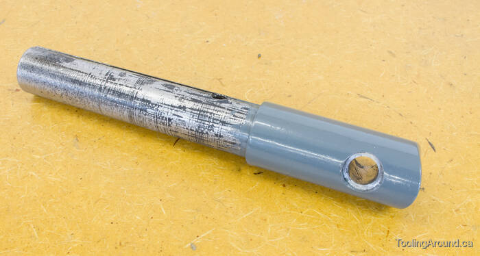
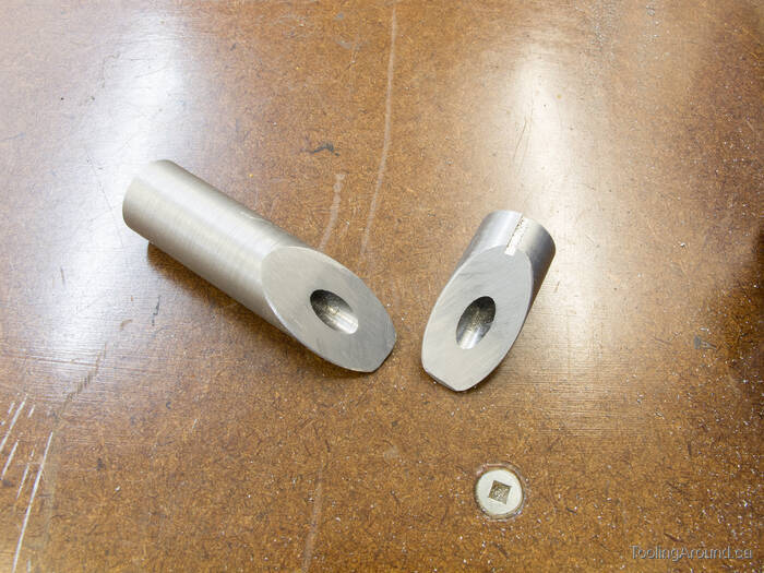
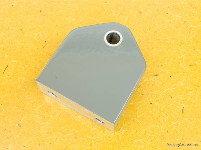
The grungy part is normally out of sight, inside the tube. The hole is for the axle and the counterbore provides a solid seat for some spacers that slide onto the axle (described further down this page).
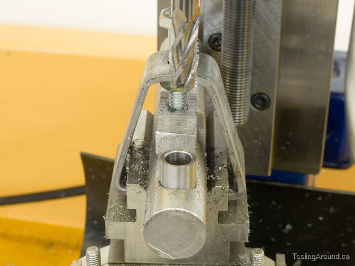
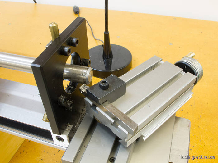
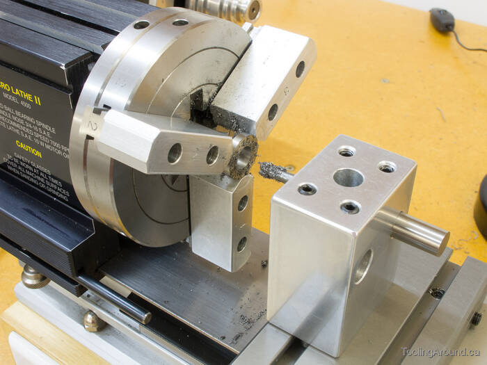
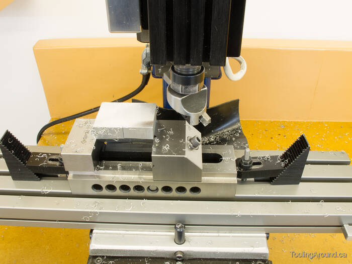
After drilling the hole for the axle, I used an end mill to make the counterbore. Here's a spacer, posing in the counterbore. This was done with the axle hole centred on the mill table.
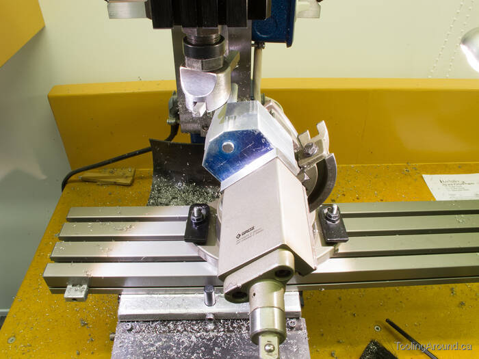
Next, I moved the mill table to position an end mill just beyond the end of the work piece. Then I moved the workpiece back toward the cutter, bit by bit, rotating the rotary table past the cutter each time, until I had formed a nice, rounded end on the work piece. Because the axle hole was centred on the rotary table, the curve on the end of the workpiece was concentric with the hole.
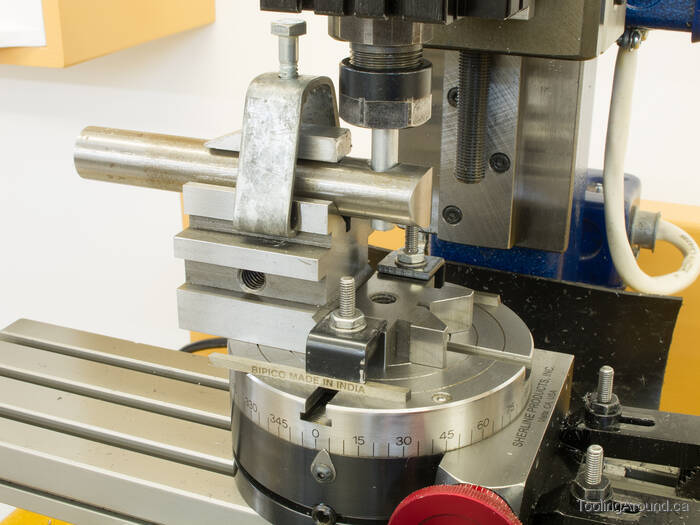
In order to cut a counterbore on the opposite side of the work piece, I inserted a scrap of 5/16″-diameter round into the axle hole and re-mounted the work piece on the V-block, with the round held in the collet. This ensured that the hole was centred under the spindle and aligned vertically. Then it was a simple matter to replace the round with an end mill and cut the counterbore.
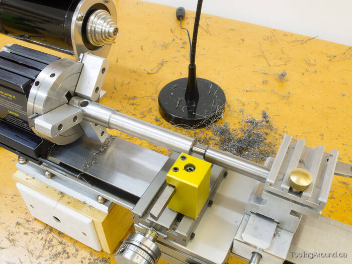
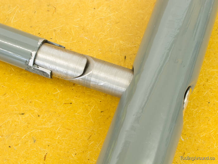
Off to the lathe to reduce the diameter of the round to slip into the handle tube.
As with the hardware at the other end of the tube, I had to cut a shallow groove to clear the weld inside the tube. In this case, however, the end of the groove stopped short of where I needed it, so I had a little bit of filing to do.
And there's how it fits. The handle tube was black, at the time, because I still hadn't settled on a suitable colour, given the limited selection of paint colours I had on hand.
Vertical Frames (Skip to "Axle And Spacers".)
The vertical frames hold the steel plate above the wheels. The design requirements are simple: provide a solid base against the plate and carry the weight from the ball to the axle.
Here's a completed frame, made from a piece of 2″ × 3/4″ aluminum bar stock.
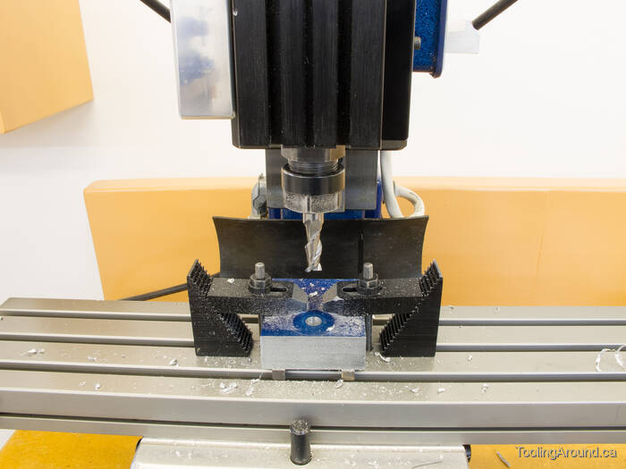
The workpiece is sitting on a pair of 1/8″ lathe tool bits to hold it clear of the mill table while drilling a hole for the axle. In this photo, an end mill is used to bring the hole to its finished size, producing a nice clean hole.
After trimming off the corners, I slid a scrap length of 5/16″ bar through the axle holes of both frames, to keep them aligned with each other. This rod remained in place for the rest of the work on the frames, starting with fly cutting one of the sides.
While positioning the work to flycut the other sides, I temporarily used a machinist's clamp to keep the sides from rotating relative to each other.
This particular machinist's clamp was made by my uncle, as a shop project while he was in high school. He wouldn't have imagined that it would still be in use.
After cutting the corners at 45°, I relieved sharp edges with a file and the frames were finished.
Most of this fly cutting was just to make the frames look nice. The only surface that really mattered was the one that would be against the steel plate. It had to be square and the distance from the holes to the ends of the frames had to be equal, so the axle would pass easily through them after they were mounted on the plate.
Axle And Spacers (Skip to "Plate".)
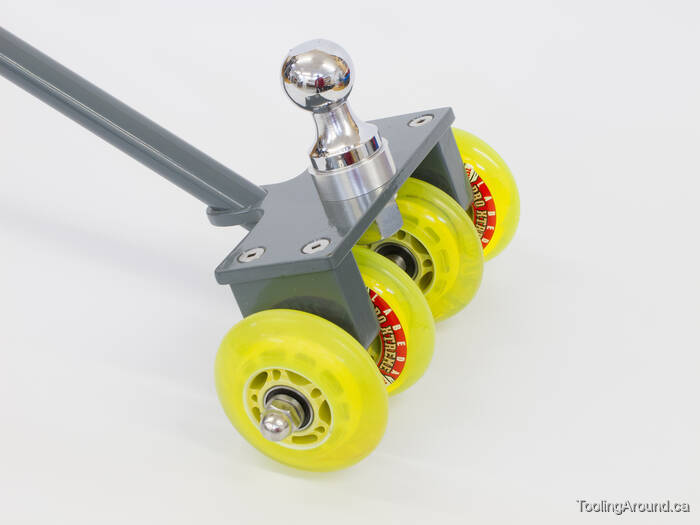
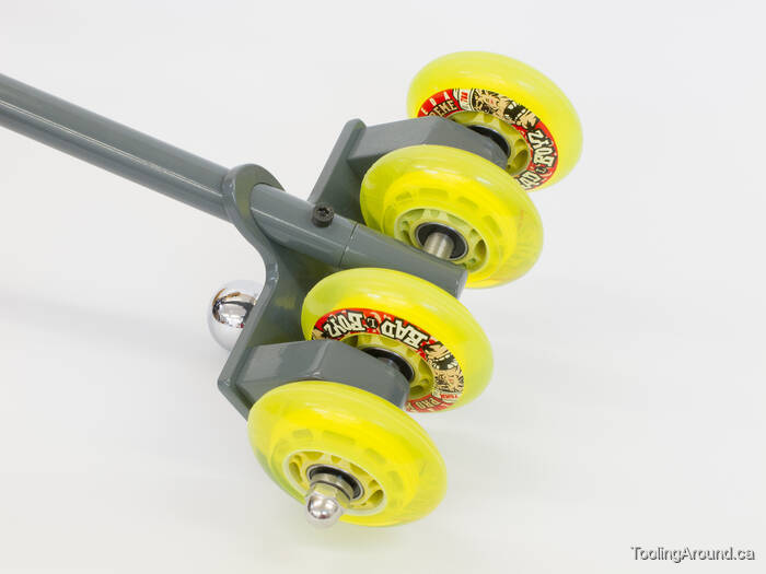
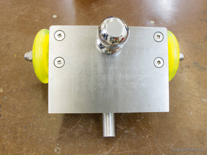
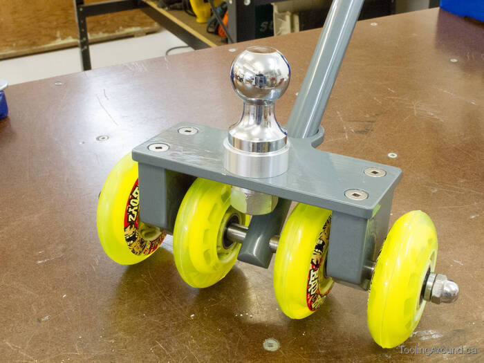
Here's the general arrangement of the handle mount, frames and wheels. The wheels have bearings on each side, so I made spacers that fit against the inner bearing races, with acorn nuts on the ends of the axle, pinching the whole assembly tightly together.
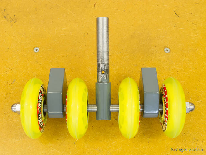
Maybe a word about those wheels is in order. Yes, they're so bright that I can practically find the dolly in the dark. They're a set of inline skate wheels that were about to be discarded at a store where one of my sons worked. Knowing that I was contemplating this project, he salvaged them for me. It was just a matter of finding some inexpensive ball bearings, which I purchased at an different store that sells skateboards. Given the expected demands on this device, I bought the cheapest ones they had and they are just fine.
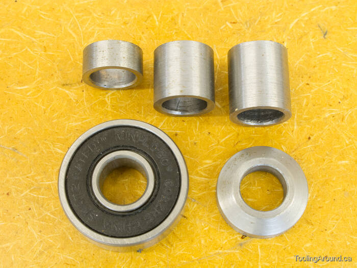
In the top row, the left-most spacer is one that keeps a wheel from rubbing on a frame, the middle spacer goes inside a wheel to keep the inner bearing races apart and the right-most one keeps a wheel far enough away from the handle mount.
The bearings are type 608ZRS. The number (i.e. 608) indicates that this is possibly the most common standardized bearing, with an 8mm bore, 22mm outer diameter and 7mm width. ″Z″ indicates that it's sealed on one side and ″RS″ indicates that it has a rubber seal.
Of all this information, the thing that matters to this project is the inner diameter. Looking at what I had available in my small stock, to use for the axle, I found some 5/16″ steel bar. I measure its diameter as 7.9mm, which makes for a loose fit in the bearings. However, it doesn't have to turn (or resist the turning of the inner bearing races); it just has to carry the load. In practice, it has been completely satisfactory.
The washer is tapered so the narrow flat will press on a bearing's inner race and the larger surface on the other side will fit against an acorn nut.
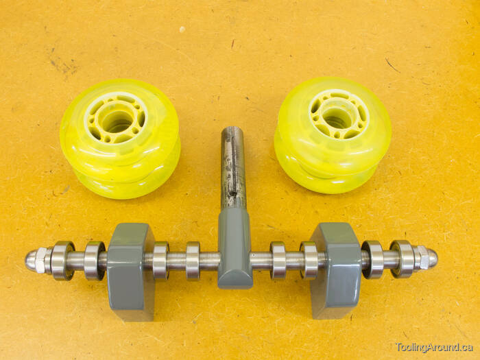
Just to be clear, here's the arrangement of all of the components that are mounted on the axle, with the wheels out of the way.
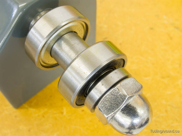
This photo clarifies how the tapered washer carries the load from an acorn nut to a bearing's inner race.
To make a tapered bearing, I used a steady rest to support the end of a length of bar stock. After cutting a taper to leave a diameter that matches a bearing's inner race, I used a parting tool the remove a washer.
After parting, the washer wasn't quite a washer, as it had no hole. In preparation for drilling a hole, I mounted it in a three-jaw chuck, using a lathe tool blank to align it with the front faces of the chuck jaws.
After drilling, I used a boring bar to bring the hole to the desired size.
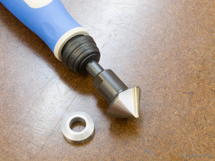
I used a Noga deburring countersink to clean up the inner edges of the hole.
Plate (Skip to "Ball".)
The plate is literally where it all comes together: the tube, the ball and the vertical frames.
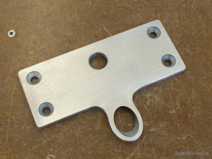
Here's the completed plate, prior to painting. It looks innocent enough, but was the most difficult piece to make because of the hole for the steel tube.
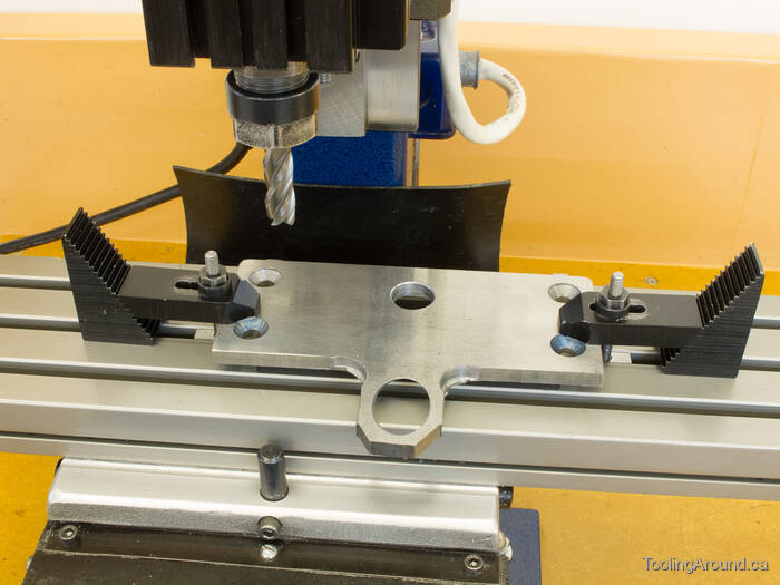
First, I drilled four holes to clear 1/4″ × 20 tpi screws. Next, I assembled the axle, bearings and spacers in the vertical frames and clamped them in position on the plate, so I could use a transfer punch to mark the vertical plates with the locations to drill and tap for the screws.
The next challenge was to drill and bore a hole for the steel tube. Because the hole would be at a 45° angle, I needed a way to hold the plate on the mill table to make the hole.
I cut two pieces of 1″ × 1-1/2″ aluminum bar to use as fixtures for the plate.
After fly cutting the bottoms, I fixed the two pieces together in the vice and milled a groove that would be the seating surface for the plate.
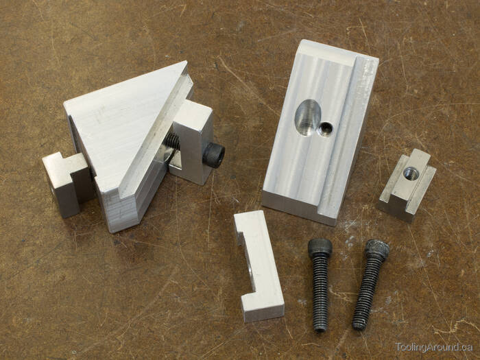
Here are the fixture pieces. The one on the left is assembled. You can see how one “leg” of each clamp is shorter than the other. The leg lengths are designed to clamp material that is 1/4″ thick.
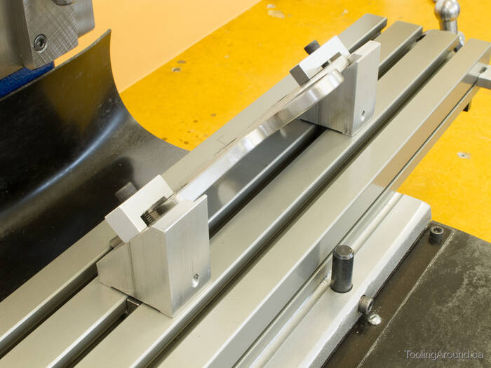
This is how the plate is fixed to the mill table. The bottom edge of the plate registers against the edge of a T-slot and the plate sits in the rebates on the fixtures.
As you can see in the photo, the plate has already been finished. I don't have any photos of the boring operation because it was actually done on a different Taig mill, by my friend, Brian Finlayson. He offered to do the drilling and boring, as he has a boring head. At the time of this project, my boring head was still a future project.
After some judicious removal of extra material by drilling a couple of holes and using my band saw, I milled the straight edges of the plate.
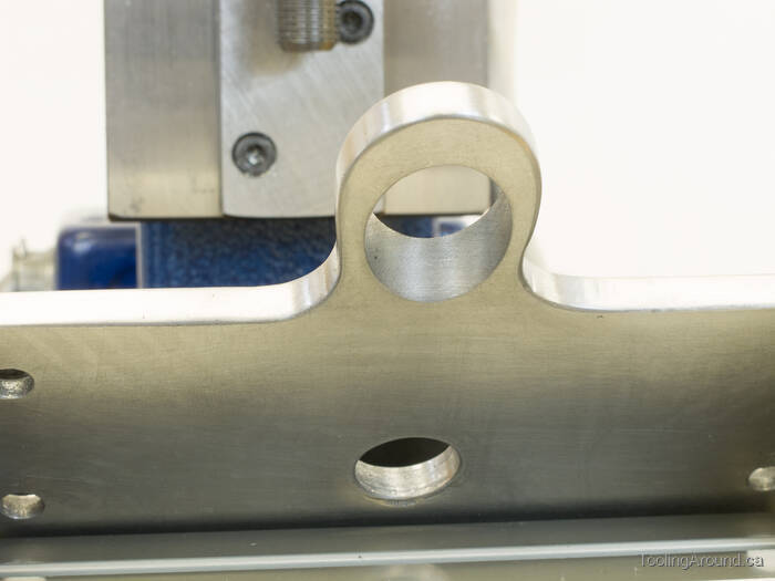
Here's the plate, after some careful filing. You can see the fine finish that Brian achieved in that bored hole.
Ball (Skip to "Sockets".)
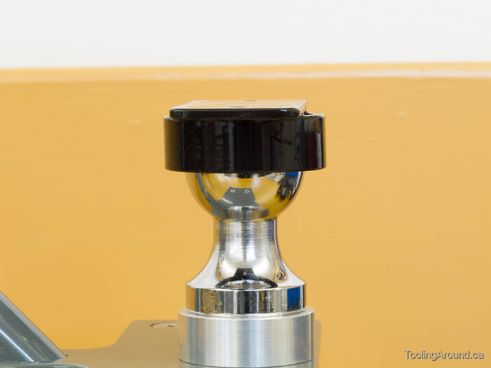
The threaded shaft of the ball is too long to fit under the plate, without interfering with the handle mount, so I turned and bored a spacer to lift the ball mount half an inch above the plate.
Aside from allowing the ball mount to fit, lifting it even this much moves it a useful bit farther away from the axle, which is the centre of rotation when tipping the ball under the edge of a socket and then tipping it upright to lift the item being moved. It makes just a bit of difference, and every bit helps.
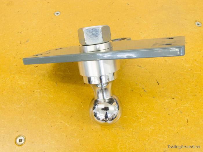
I turned and bored an aluminum washer to fit under the nut. The ball came with a lock washer, but it's overkill in this application and would definitely damage the plate.
Sockets (Skip to "Finished!".)
Okay, these aren't actually “sockets”. If this trailer sway bar ball was used as intended, it would fit into a socket that would hold it securely while still letting it swivel. However, my shop floor is smooth and has no potholes, so I'm not concerned about the possibility of the socket bouncing off the ball.
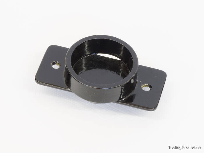
As you can see, the socket is just a ring on a plate.
After cutting some short lengths of 1-3/8″ steel gas pipe, I faced the ends true, to achieve a final length of 14mm.
Just an aside: yes, sometimes I measure in inches and sometimes in millimetres (my preference). It's some fun, living in a country that theoretically converted to the SI system of measurement starting in 1970, but is still somewhat stuck with the old system, even after all those years, partly due to inertia and partly due to the influence of our neighbour to the south. Many supplies are made to American specifications and sometimes I end up using a mixture of measurements. Sometimes, especially, it seems, in the building trades, materials are made to be compatible with existing construction. This leads to such things as plywood sheets that measure 4′ × 8′, but with thicknesses specified in millimetres, not fractional inches. For example, what used to be 3/4″ plywood is now actually 19mm.
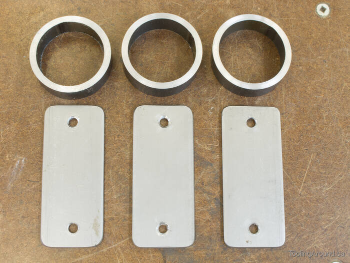
Three sockets will be a good start.
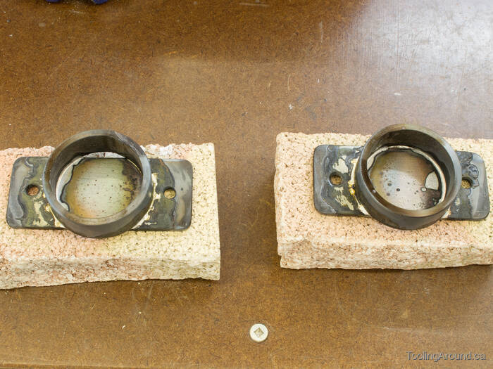
Cooling down after silver brazing.
They're just deep enough to allow the very edge to touch the widest part of the ball. If it looks like the socket is sitting strangely low on the ball, it may be because the ball has a flat spot on top. As it turns out, this makes an ideal bearing surface, against the steel plate at the base of the socket.
Finished!
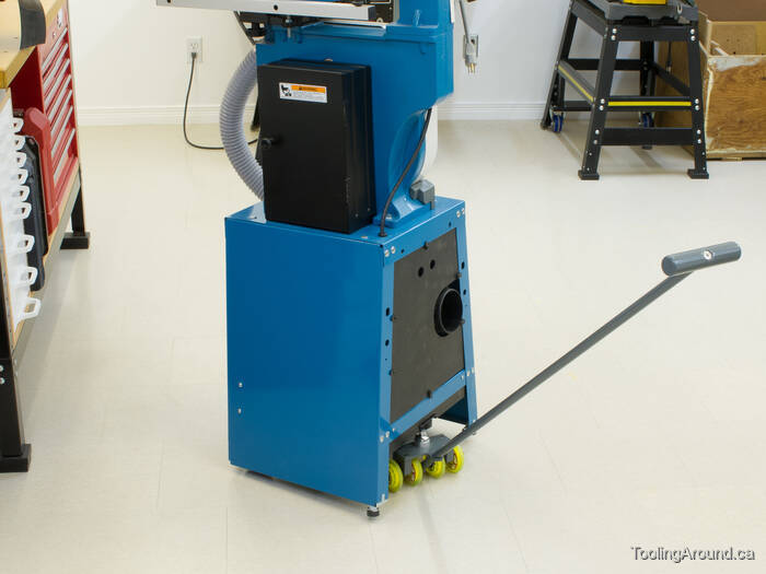
How to attach the sockets is another story, but the resultant ease of movement of pretty heavy loads has to be experienced to be appreciated. It makes it entirely practical to put large tools out of the way and there's absolutely no impediment to just pulling them out when they're needed. There's no risk of damage to the tool or my back.