 Tooling Around
Toyo Lathe – ER-16 Adapter
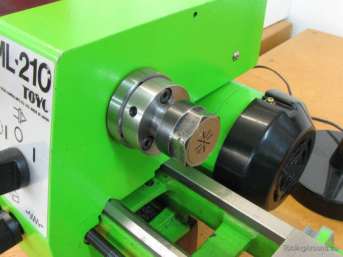
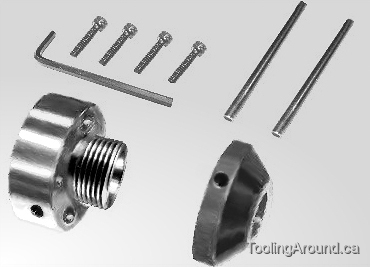
Collets provide an excellent way to hold small work in a lathe. They are inherently self-centring and the absence of chuck jaws makes for an altogether more comfortable experience in tight quarters. It's poor style to get blood on your work. Toyo collets were available as an accessory, as shown in these photos from the instruction manual. (My thanks to John Bentley for his excellent enhancement of the original halftone images.)
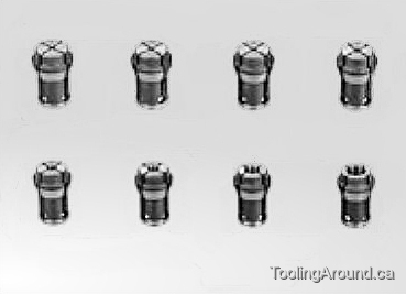
Now, the Toyo collets were no longer available, but I had a set of ER-16 collets for my Taig mill, so I decided to make an adapter, similar to the one offered by Toyo, so I could use them on the lathe. The maximum capacity of ER-16 collets is 10mm, which is an excellent match for the lathe spindle's 10.5mm bore.
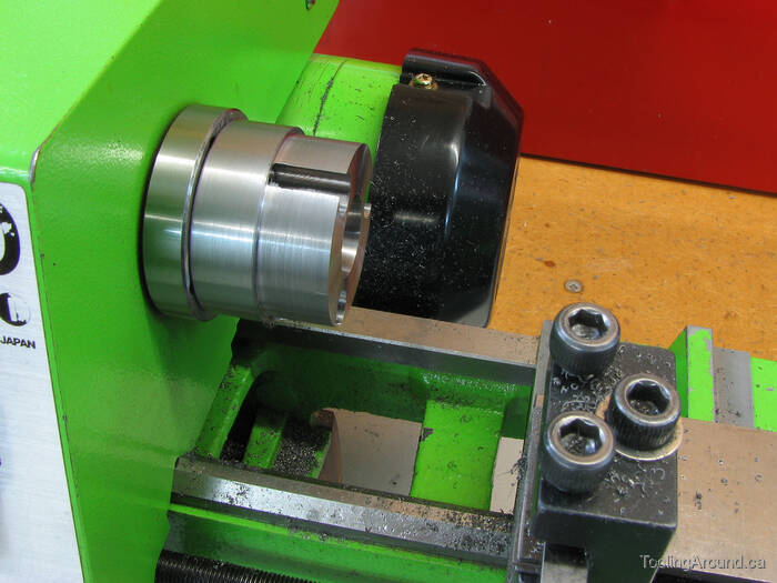
The first step was to drill and then bore a recess to match the lathe spindle nose. On the Toyo lathe, a chuck is not threaded onto the spindle, as on many other lathes. Instead, it slips over a protruding central portion of the spindle nose and is held in place by cap screws. For good registration, it's important to achieve a close fit between the chuck and this part of the nose. The same is true of this collet adapter.
To achieve the best fit I could, I bored the recess on the Taig lathe, increasing the diameter of the bore until it was as close to the desired diameter as I could get while remaining undersized. Then I removed the workpiece from the Taig lathe by unscrewing the chuck and checked the fit against the Toyo lathe spindle nose. It was important not to remove the workpiece from the chuck, as it would have been essentially impossible to centre it precisely, again. As I got close to the final size, I increased the bore by .001″ or less at a time, checking the fit each time, until I had a close, sliding fit.
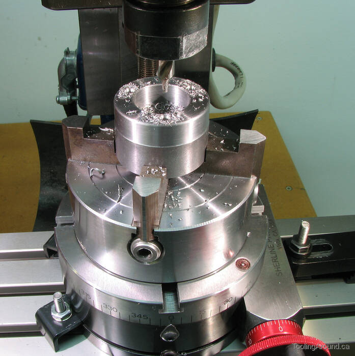
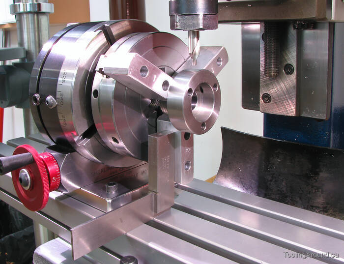
With the workpiece still undisturbed in the chuck, I mounted the chuck on the Sherline rotary table and centred it under the mill spindle. Then I moved the table by an amount equal to the desired radius of the mounting holes circle. Rotating the table 120° between holes, I used a centre drill to start each hole and then drilled the appropriate size holes all the way through the workpiece. Finally, I used an endmill to counter bore each screw hole to accommodate the SHCS heads.
You may have noticed that I chose to mount the adapter with three cap screws instead of the four used by Toyo. There's no particular reason for this decision. The spindle nose is drilled and tapped for both options, since one is used for fitting the three-jaw chuck and the other for the four-jaw chuck.
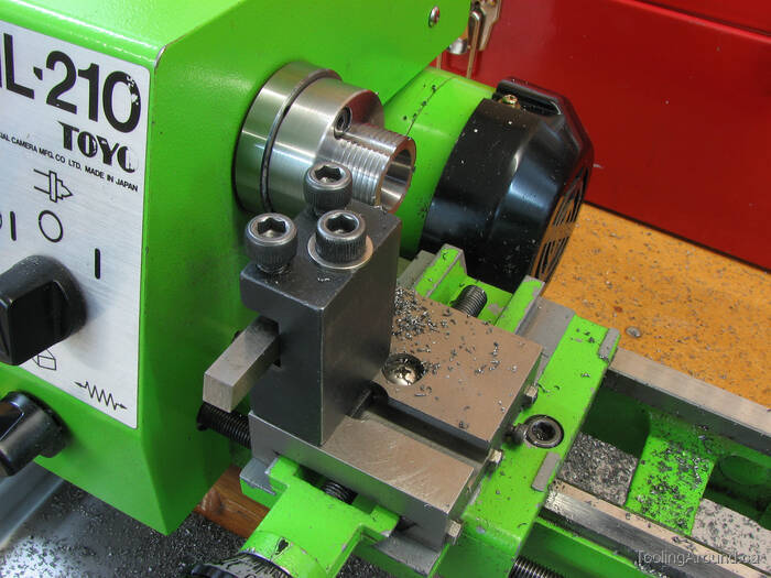
The workpiece is now mounted on the Toyo lathe. This mounting will not be disturbed until all of the critical machining operations are complete. This helps ensure that the collet taper and threads will be concentric with the spindle.
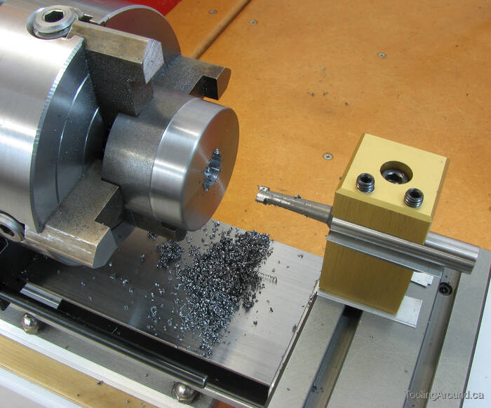
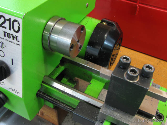
In this photo, a facing cut has just been made, to dress the end of the adapter.
The top slide has been set to the angle required for boring a taper that will match an ER-16 collet. The technique I used to set the angle was by direct measurement of a collet. That is how I did it when making a tool holder for the Taig mill. The technique is described on the Aligning A Top Slide page.
To bore the taper, the top slide is backed off at least the length of the eventual taper. Then the carriage and cross slide are adjusted to bring the tip of the boring tool to the edge of the previously bored hole. The carriage is then locked in place, where it remains until the taper boring operation is complete. Now the taper boring can begin. The first cut just nips the sharp corner off the hole. The top slide withdraws the cutting tool and the cross slide is adjusted to increase the depth of cut.
The bore diameter is gradually increased and a collet is placed in the hole from time to time until it is almost seating far enough. By the time I got to this point, I was removing very small amounts, so as not to overshoot and produce too large a taper. When getting to these fine cuts, it's a good idea to lock the cross slide for each cut, only releasing it to adjust cut depth.
Make an extra pass with the top slide each time. This extra pass is called a spring cut, the idea being that a cutter will deflect a bit as a cut is made and spring back when the tool is withdrawn. The amount of deflection will depend on the stiffness of the cutter and the depth of cut. A long, thin cutter making a deep cut will deflect more under the pressure of cutting forces than a stubby, thick cutter making a light cut. Anyway, without changing cut depth, run the tool back through again, presumably taking just a whisker of a cut because the tool has sprung back. To be honest, I was already taking such light cuts by this point that I'm not sure it made any difference, but I did it anyway, to be sure.
The diameter of the part to be threaded is gradually reduced in preparation for threading. I determined the desired diameter by measuring the diameter of the Taig mill spindle nose.
As you can see, the cut has progressed into the holes produced when counter boring for the heads of the mounting screws.
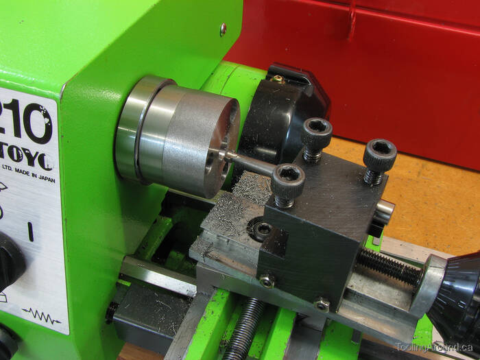
Cutting the M22×1.5 thread.
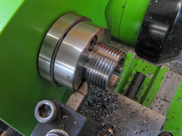
The threads are approaching their full depth.
This is a good place to point out an error. Did you notice it? Just to the left of the cutting tool, in this photograph, you should see some relief so the cutter can run off the end of its cut into open air. I did eventually provide this relief, but forgot to do so prior to threading. Live and learn. You can see the corrected relief on the completed adapter near the end of this page. A relief groove was cut using a parting tool.
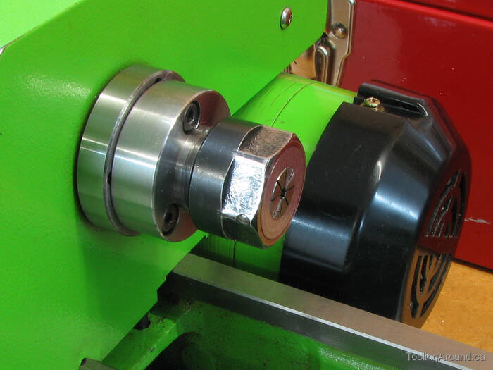
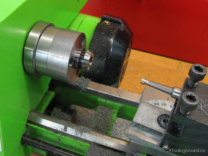
Here's a test fit of a collet nut holding a collet.
The adapter is ready for use, except for one detail. I need a way to keep the spindle from turning when tightening or loosening the collet nut. The solution is the tried and true tommy bar.
The adapter has been removed from the Toyo lathe, reversed, and mounted in a Taig three-jaw chuck. The jaws are gripping in the grooves that remain in the collet nut threads. The chuck is attached to a Sherline rotary table, which is attached to a vertical adapter, which is attached to the mill table.
This means that, by aligning the chuck so one jaw is vertical, as shown here, a hole drilled into the adapter body will be half way between two mounting screw holes. Not that we need to be terribly fussy, but this will be very close.
Spot drilling a tommy bar hole, using a centre drill bit (a.k.a. Slocombe drill bit). It would be more correct to use a spot drill bit; if and when I get some, I shall do so.
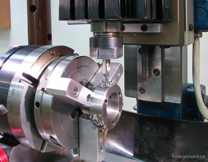
The rotary table is advanced 120° for each successive hole. The process is repeated, using a twist drill bit, to enlarge the initial holes and reach the required depth for tommy bars.
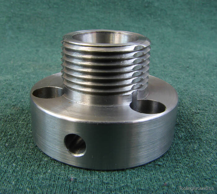
In this side view of the completed adapter, you can see that the threads have been nipped by the initial countersinking of the mounting screw holes. This has a negligible effect on the strength of the threads.
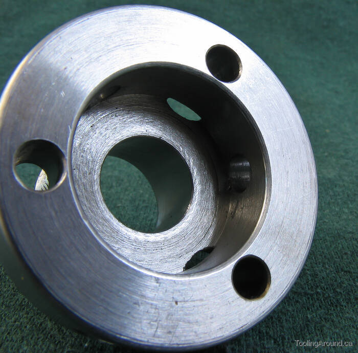
This bottom view shows that the recess for the spindle nose my be just a tiny bit too deep, as there are holes where the counter bore came through. Or maybe the counter bores are just a tiny bit too deep. You decide. In practice, it works just fine.
In use, the adapter has been successful. Were I to do it again, I would provide thread relief next to the adapter body before cutting the threads and I would counterbore just a tiny bit short of what I did this first time. Otherwise, it's fine.
When I'm being fussy, I use a DTI to check centring when mounting the adapter. A gentle tap with a small brass hammer is enough to correct any minor mis-alignment. Then I snug up the mounting screws. Mis-alignment is on the order of .001″, which doesn't disappoint me. Some clearance is needed to get the adapter onto the spindle nose.