 Tooling Around
Part 2 – Pedestal Boring
The challenge I had was to make two pedestals that together would support a shaft. The challenging part was to get the bore for the shaft precisely in line and the correct diameter. It seemed to me that I should bore the holes through both pedestals at the same time and that led naturally to the use of a boring bar, which I did not have. So, I stopped work on the motor mount and made a boring bar.
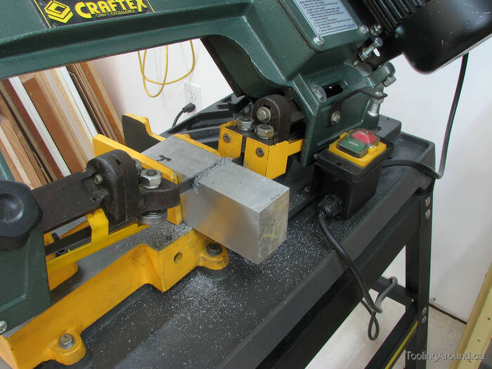
The project started, as so many do, at my trusty bandsaw. This chunk of aluminum came from the cut-off table at a nearby industrial metal supplier. Translation: I'm not sure what grade it is. As I discovered, it's somewhat gummy.
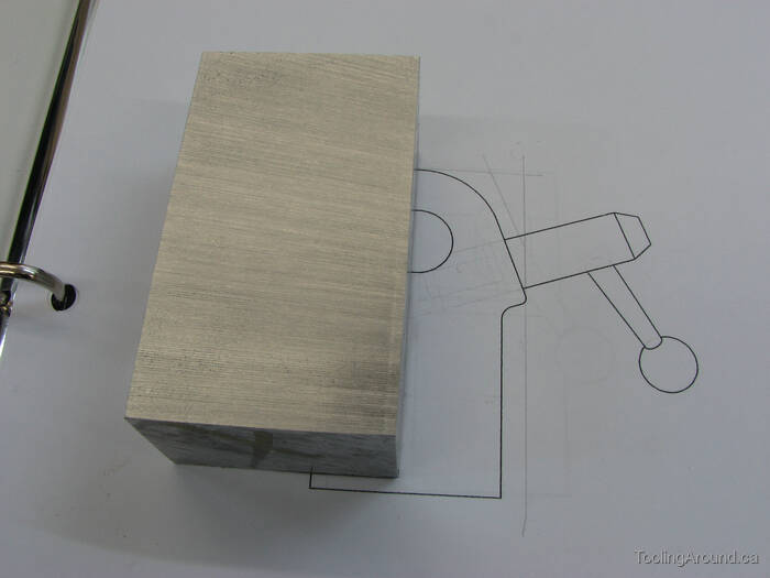
Inside this lump of aluminum is a nice, new pedestal.
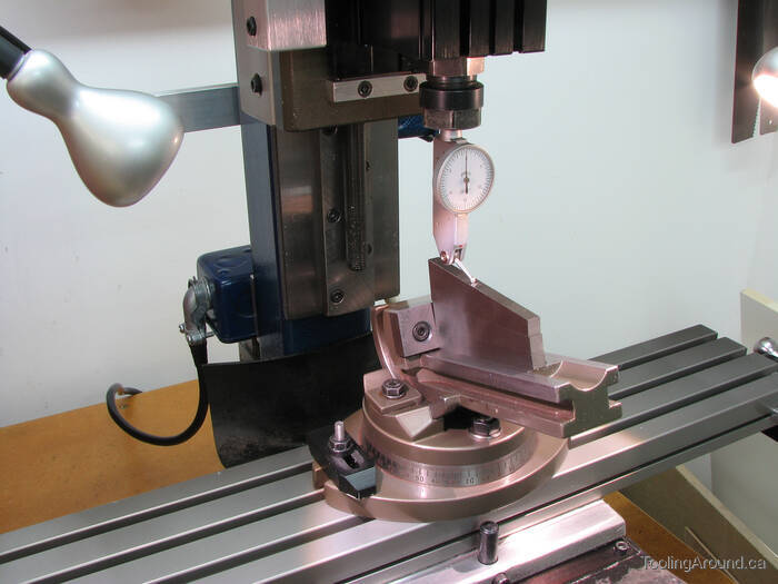
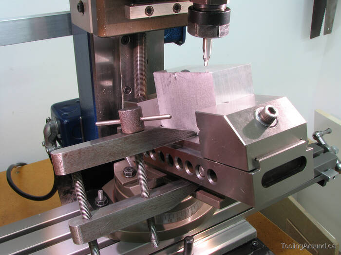
To set the angle of the vise accurately, I stacked the appropriate angle blocks on the vise and used a TDI to set the top of the stack level. I just moved the table back and forth under the indicator tip, adjusting the vise angle until the reading on the TDI remained stable as the table moved.
Incidentally, note the angle of the TDI's tip relative to the angle block. For best results, the angle should be as shallow as reasonably possible, as shown here.
In this case, I stacked three blocks, a 10°, 8° and 7° block, for a total of 25°.
This is an awkward way to hold the workpiece, but it is effective. The problem is that the workpiece was too long to fit lengthwise in the tilting vise. The better way to do this would be to use a three-way tilting vise, but I didn't have one, at the time.
Anyway, I've set it up to drill a hole for the split cotter. The hole is at an angle because I want the split cotter to tilt upward, getting the handle away from the base.
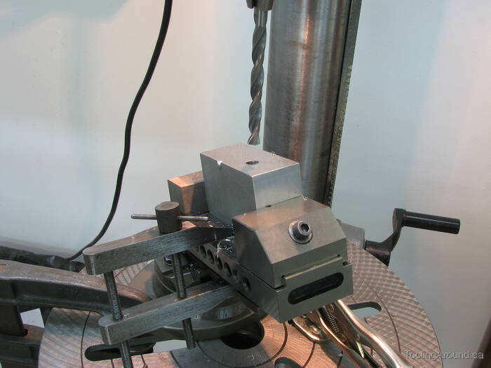
One of the realities of a small mill is the limited work envelope, so it was off to the drill press to use a larger (and longer) bit.
A bar has been inserted into the hole for the split cotter. The split cotter will be made from this bar, but rather than cut off the portion needed, I left it intact, to be cut later.
As you can see, the hole is not true where the bar enters the block. If I remember correctly, I had a problem with the drill bit deflecting as I drilled the hole. It would have been better to have milled a flat prior to drilling. As usual, hindsight is 20/20. Fortunately, this part of the pedestal will be removed, later, including the malformed part of the hole.
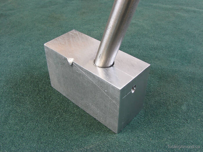
Note the small hole in the end of the bar. It has been threaded 10-24 for a grub screw. The purpose of the grub screw is to fix the bar in position during the boring operation to follow. Later, the grub screw will be removed and the part of the block that it occupied will be completely cut away. You can see a line scribed on the side of the workpiece, showing where the cut will be made.
A length of aluminum bar stock has been cut for the other pedestal. The pedestals have been clamped together and the bottoms of the two of them are being flycut. This ensures that they are in the same plane.
After flycutting, three holes were drilled in the base of each pedestal, without disturbing the setup in the mill.
Without disturbing the clamp, the pedestals were turned 90°, so their backs can be flycut. Once again, this ensure that the backs are in the same plane on the two workpieces.
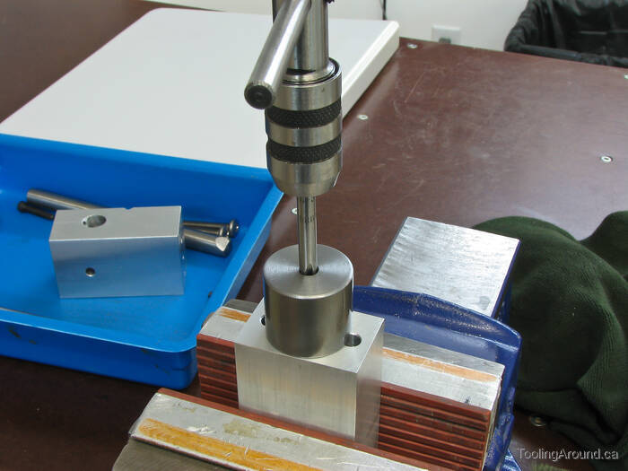
Lacking a tapping stand, this is how I keep a tap lined up with a hole. It's a more or less satisfactory method.
The centre hole on each pedestal will be used to fasten the pedestal to a base. The other two holes will contain steel dowels that will mate with holes in the base, to keep the pedestals aligned.
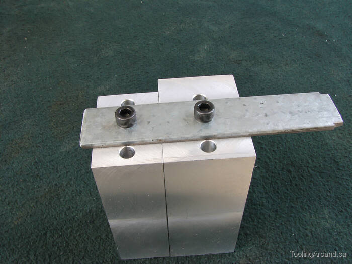
The pedestals are bolted to a scrap piece of steel bar. This ensures that they're kept in line for the boring operation.
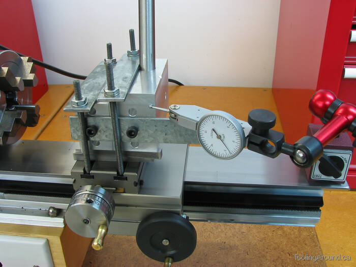
This is a bit of a lashup. The pedestals are sitting on two pairs of lathe tool blanks, to raise them to the desired height. You will recall that the backs of the pedestals were flycut so they would be in the same plane. This is why; when held down against the tool blank packing, the pedestals will be aligned with each other. Two lengths of steel strap hold the pedestals to the lathe cross slide.
The TDI is being used to align the bases of the pedestals with the centre axis of the lathe. The carriage is run back and forth with the TDI reading from the pedestal base, adjustments being made until the needle is motionless.
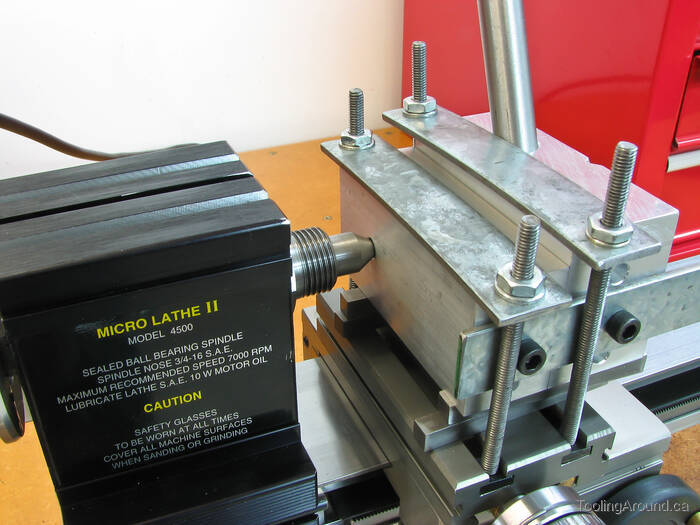
Prior to mounting the pedestals on the carriage, I drilled a pilot hole where the final hole would eventually be bored. In this photo, the cross slide has been moved to place this hole on the spindle centre. Then the cross slide was locked in position.
The next step was to drill the initial hole progressively larger until the boring bar could be inserted.
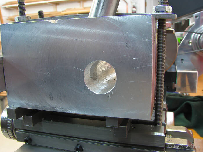
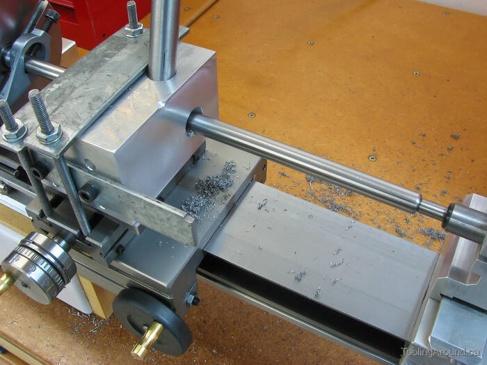
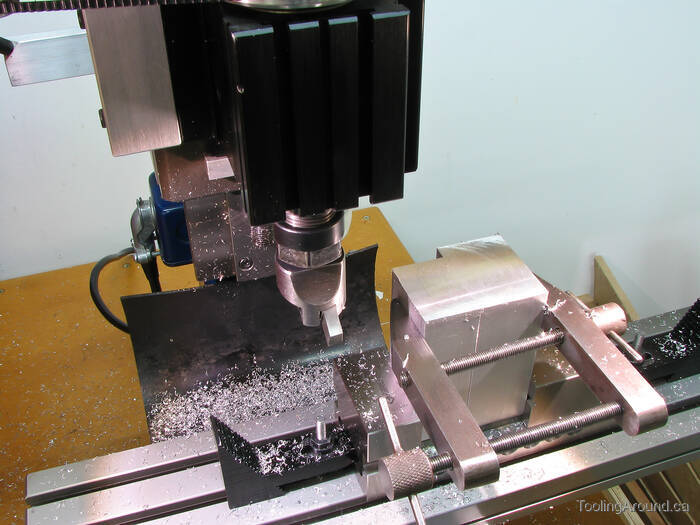
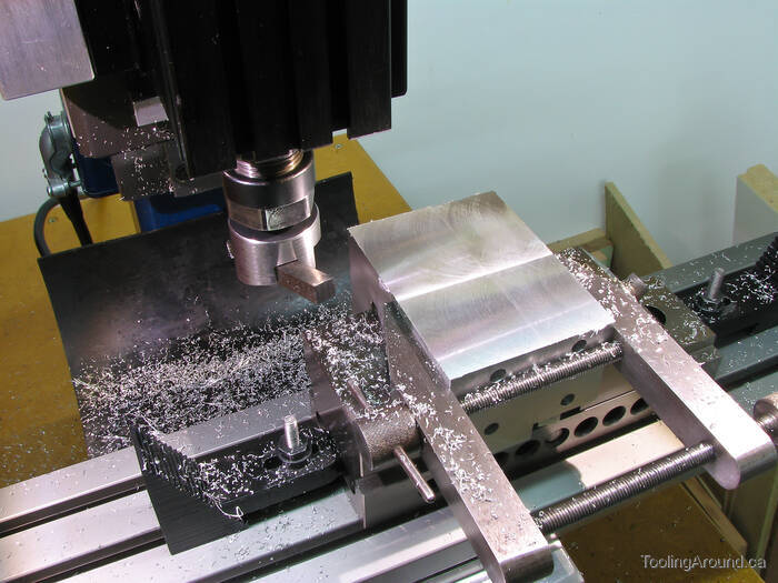
As you can see from this photo, the boring operation is complete. However, the finish is not nearly as good as I would have liked. This was my first attempt at the use of a boring bar. You can read about it here.
Finish aside, the hole is entirely serviceable, given its purpose. The interesting thing to notice is that part of the fixed-in-place rod has been removed during boring. This is a necessary part of making the split cotter, which you will see, later.