 Tooling Around
Taig Lathe – Tailstock Modifications
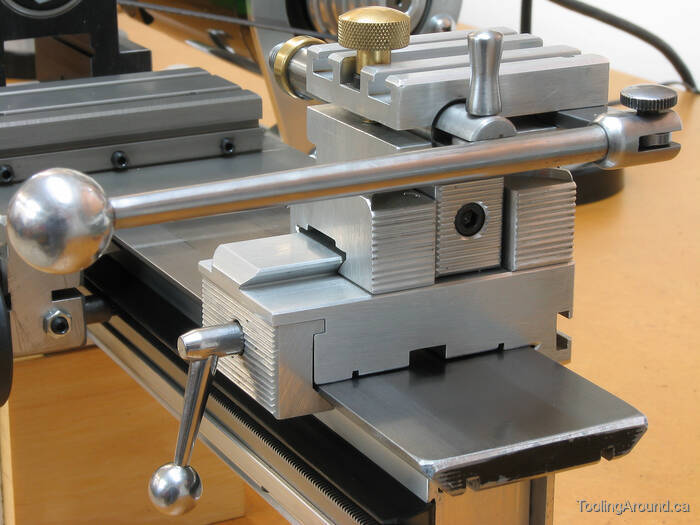
Here are the two modifications: a ball handle for the ram and one for the attachment to the lathe bed. The former is more comfortable on the palm of your hand. The latter is much quicker to use than a wrench.
I've provided some dimensions along with the descriptions. If you decide to make your own, don't be too concerned about the size of mine. Just use the dimensions as a guide.
Ram Handle (Skip to "Fixing Bolt".)
The stock handle for the ram is simple, effective and uncomfortable.
The end of this handle will rest in my palm, so I chose to use a 3/4″ polish ball. My thinking was that this would allow me to use a fair bit of pressure without discomfort and that has proven to be the case.
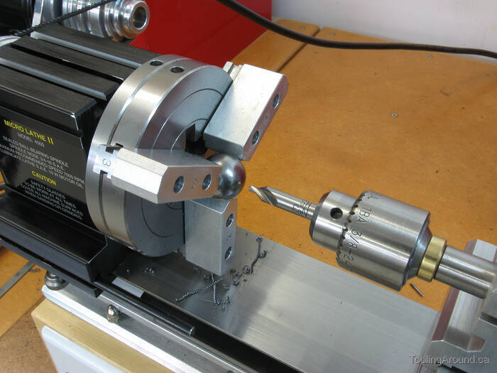
The first step in making the handle was to drill a hole for mounting the ball.
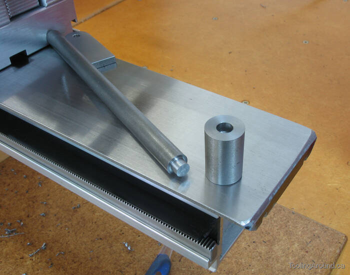
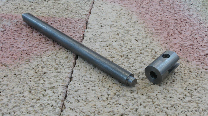
This is the handle's shaft, yet to be tapered. The thicker piece is for the pivot end, with a hole to accept the stub end of the shaft.
Both pieces are made of 12L14 steel. The thick piece is a bit over 3/4" long, with a 1/2" diameter. The handle's shaft is a bit under 4-1/2" long, not including the stubs, and is made from a length of 3/16" round.
Checking the fit of the handle and the shaft.
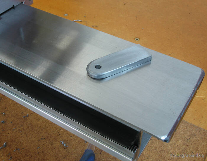
This link will attach the end of the handle to the tailstock. It's made of a bit of CRS, about 1/2" wide by 0.136" thick (by the time it was ground to fit in the tailstock) and 1-1/2" long.
One end is square – I no longer remember why. The only thing I can think of is that I left it that way until I had ground it thin enough to fit the slot in the tailstock body. Once I could get it in, I could determine the location for the hole for the roll pin and then round the corners.
Each end of the link was ground to the correct thickness, one to fit the tailstock and the other to fit the end of the handle. This was done with care, to ensure a close fit to minimize play in the joint.
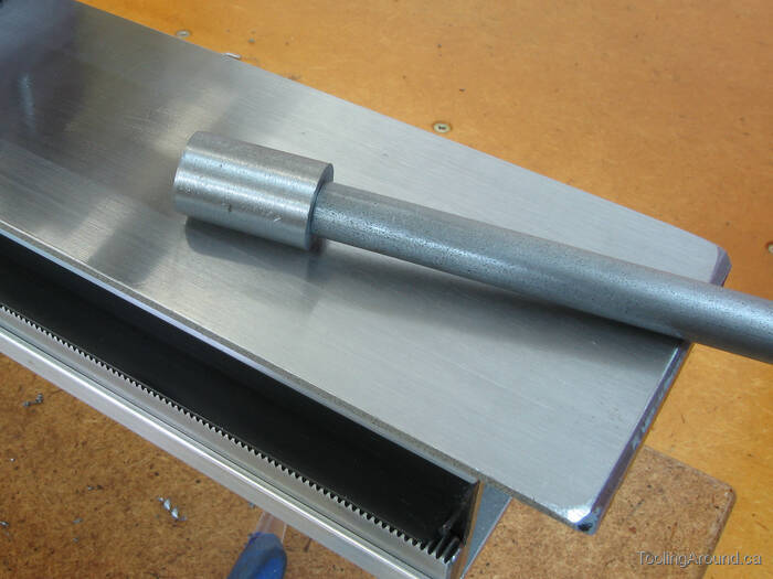
The pivot end is ready to be silver brazed to the handle. The slot is for the link that will join the handle to the tailstock.
The brazing material has nicely penetrated the joint.
The angle is formed by fire bricks, standing on edge. I normally use a double layer horizontally, as a base, and vertically, as a back. In both cases, where there is a gap between two bricks, I overlap the gap with the second set of bricks, so a jet of flame will not get by during brazing. Setting up a corner for the workpiece helps contain the heat around the work, making for easier brazing. At least, that's been my experience.
If I remember correctly, I turned the taper on the handle after silver brazing the pivot end. The taper extends about 2-1/2" from the end where the ball will be attached. This is too far for the Taig top slide to handle, so I probably “free handed it” by adjusting the cross slide as I advanced the carriage. Then, at a slow spindle speed, smooth it with a file and finish with emery paper.
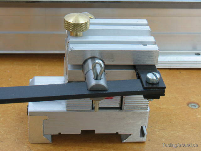
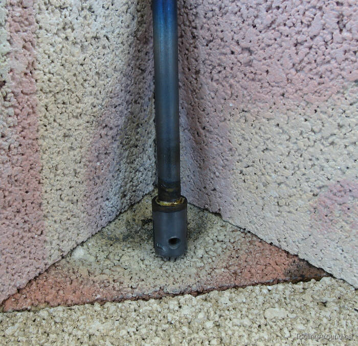
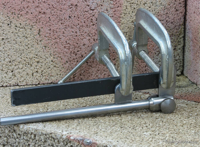
This photo shows how I set up the pieces to silver braze the tab to the handle. The rounded end of the tab will fit into the slot in the end of the tailstock ram.
An explanation of the setup would be in order. The link is in the slotted end of the ball handle, held in place by the knurled screw (which I found in my scrap box). The tab that will be silver brazed to the handle must be in the same plane as this link. So, I clamped both the link and the tab to the black bar in order to achieve this alignment. (Yes, the black bar is the original tailstock ram handle.)
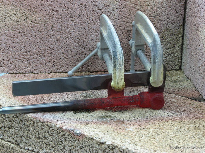
The handle is still glowing red, but it's actually cooling after a questionable attempt at silver brazing.
Although the setup with the clamps seemed to make sense, you can see in this photo that heat is being drawn from the tab by the clamp – note how the tab darkens under the clamp, indicating that it's cooler there. Being a neophyte, I didn't appreciate this at the time. To me, although I did have a join, it didn't look quite right. One solution might have been more heat, but I don't know if my propane torch could have produced any more.
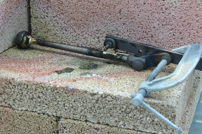
Doubting the integrity of the joint, I decided to try again. This arrangement is like the earlier one, but using a screw and nut, instead of a clamp, to locate the tab. Note that the tab was already brazed in place and this arrangement was just to ensure that it didn't shift when it was reheated.
Further proof of my neophyte status, if it's needed, is the excessive amount of brazing material. After thoroughly scrubbing the handle in soapy water, I paid for this exuberance by spending some time with small files, carefully working my way down to bare steel. It cleaned up well and I learned a worthwhile lesson.
This steel pin joins the tab on the handle to the tailstock ram, replacing the stock cotter pin.
It's 1.2" long, overall, the narrow bit being 0.155" dia. and the maximum diameter of the fat end being 0.3" dia.
Fixing Bolt
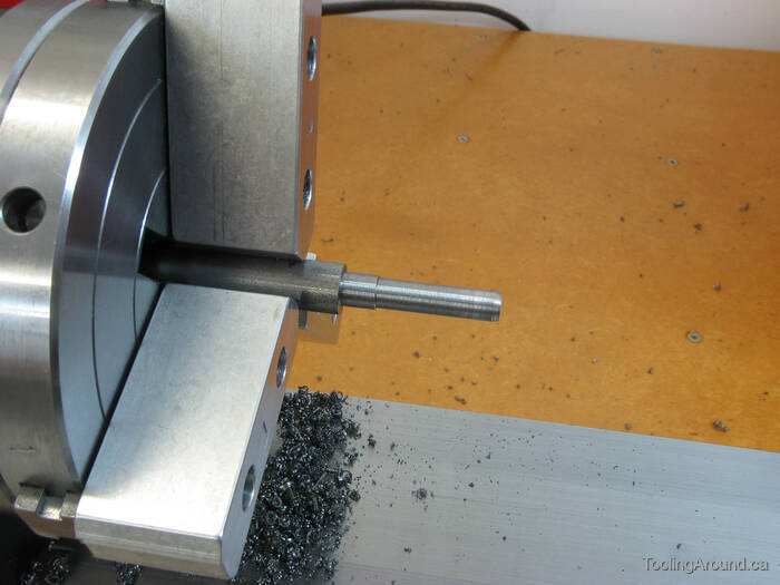
The first step in making the small ball handle was to turn the threaded shaft. This shaft will replace the stock SHCS.
It's made of a length of 12L14 steel, about 1.7" long, with a 0.3" dia. One inch of this length was turned to a smaller diameter and threaded to fit the tailstock
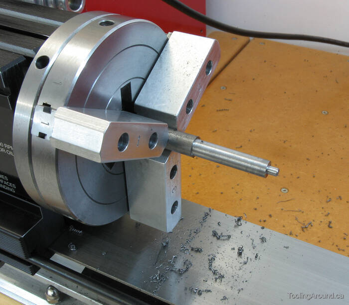
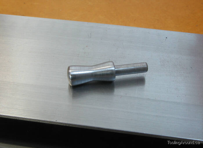
The ball handle's shaft was turned to a suitable diameter along its entire length. The ball will be fitted to the small end.
The shaft was made of a length of 12L14, about 1.1" between the 1/2" polish ball and the threaded shaft. The fat end has a 0.25" diameter and the diameter of the small end is 0.145".
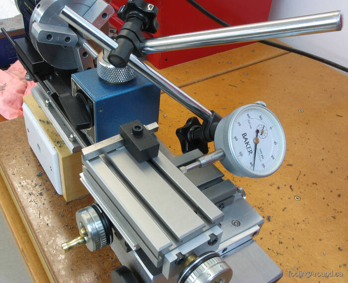
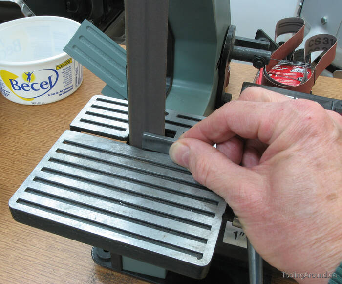
The next step was to taper the handle's shaft. In this photo, I'm setting the angle for the desired reduction in shaft diameter toward the ball end. (You can read about the technique here.)
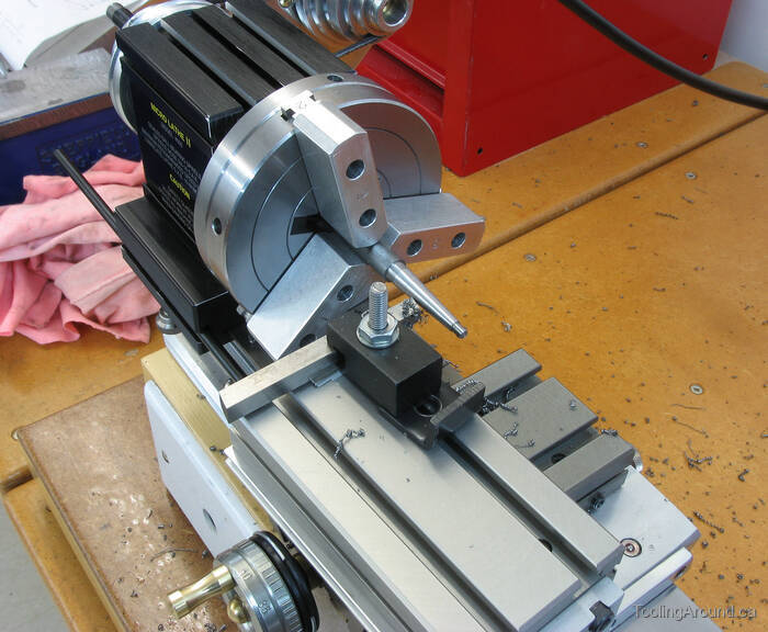
The shaft is tapered to just shy of the small section that will fit into the polish ball.
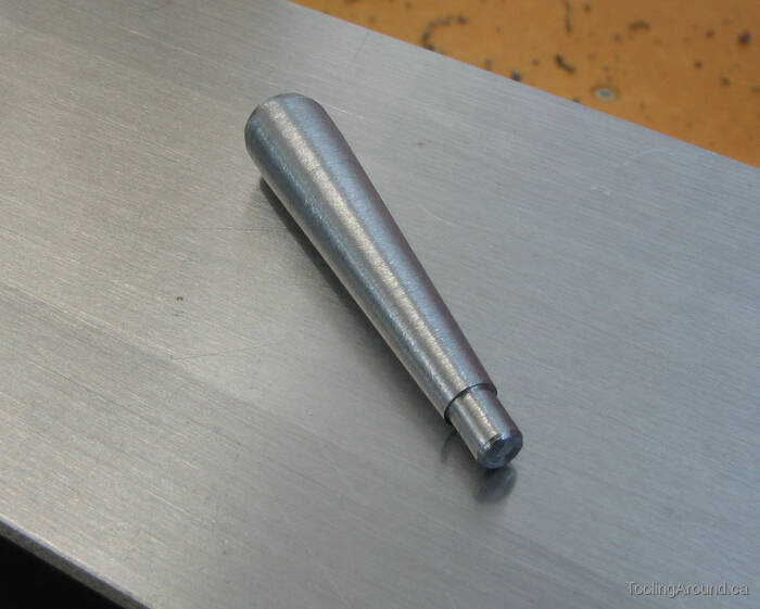
The ball handle shaft is finished.
If you look closely, you'll see that the tapered portion is slightly undercut at the small end, rather than being cut at 90° to the narrower portion. This is to ensure contact with the polish ball when the shaft is inserted. If it weren't undercut, contact would be made around the circumference of the little spigot and the round ball would fall away from there, leaving a gap. It makes no functional difference, but this looks better.
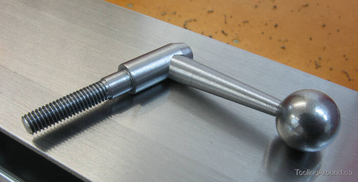
Here's a test fit, prior to silver brazing. The handle is probably about 15° off being at a right angle to the shaft.
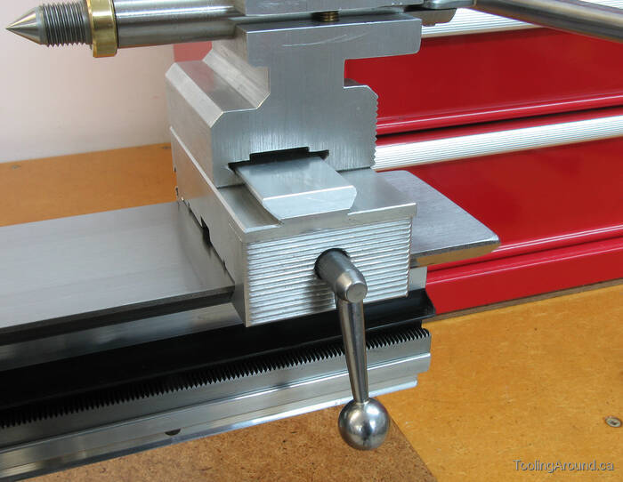
It's installed and looking pretty good.
When tightened the handle points more or less straight down. The way to make the required adjustment so this will happen is to use a washer between the shoulder on the screw and the surface on which it bears. This is desirable in any event, to avoid galling against the aluminum. All you have to do is vary the thickness of this washer, either by choosing an appropriate washer or by choosing one that's a bit too thick and reducing its thickness bit by bit until it works as desired.