 Tooling Around
Taig Lathe – Lathe Tool Sharpening Jig
There really is no substitute for sharp tools, especially on small, low-powered equipment, where we want to minimize cutting forces. For me, it has been a bit of a challenge to consistently get lathe tool relief angles right and I have not always sharpened them as soon as I should have. As they became dull, the change would gradually sneak up on me and the best time for sharpening would have passed by the time I was really aware of it. I should be more observant.
Fortunately, I have very capable friends. Keith Brooke did some excellent work, developing the sharpening techniques that are posted on Nick Carter's site. Brian Finlayson made a derivative jig, which I have more or less reproduced here.
The idea behind this jig is to use a drill press or mill to spin a diamond-coated wheel in a horizontal plane, using the underside of the wheel to sharpen the lathe tool. The height of the wheel can be adjusted precisely, especially if you're using a mill, allowing the removal of tiny amounts of the tool. The purpose of the jig is simple: to provide mounting positions for a lathe tool bit that will present its top, side and end to the abrasive wheel at the correct angle to produce the desired relief angles. Because these angles can be reliably repeated, sharpening is simplified and repeatable.
Much has been written about the ideal angles for cutting tools. In a production environment, where high speed is a major consideration, it's important to pay close attention. However, for this jig, I've kept it simple and all relief angles are seven degrees. Of course, if you choose to make one (or more) of these jigs, you can adapt the idea to the angles that you prefer.
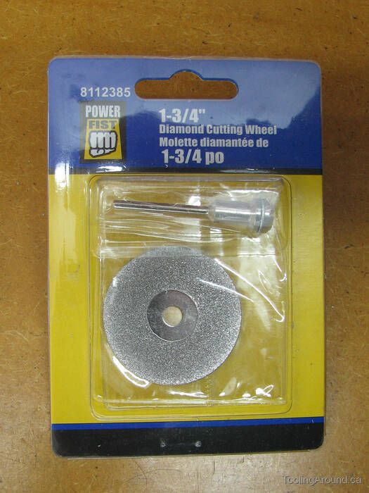
These little diamond-coated cutting wheels are the key to the project. They are inexpensive and capable of sharpening not only steel bits, but carbide ones as well.
Although they are sold as “cutting wheels”, for our purposes the flat side of the wheel is used. All that's required is to provide support for the wheel, so it doesn't deflect because of pressure on its side.
The Jig (Skip to "Wheel Holder".)
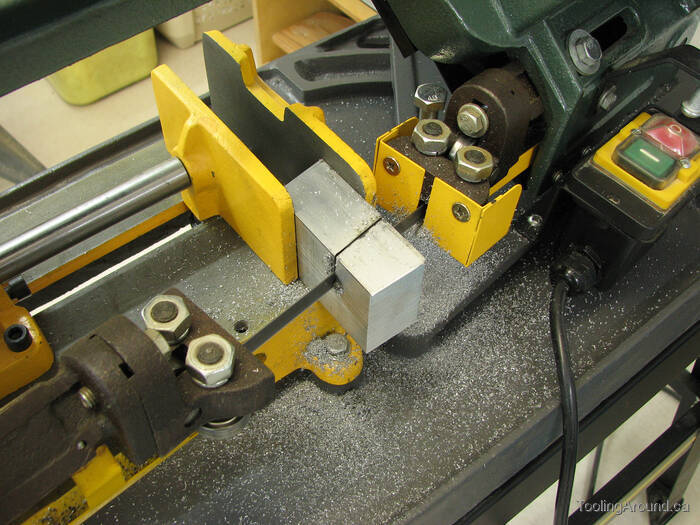
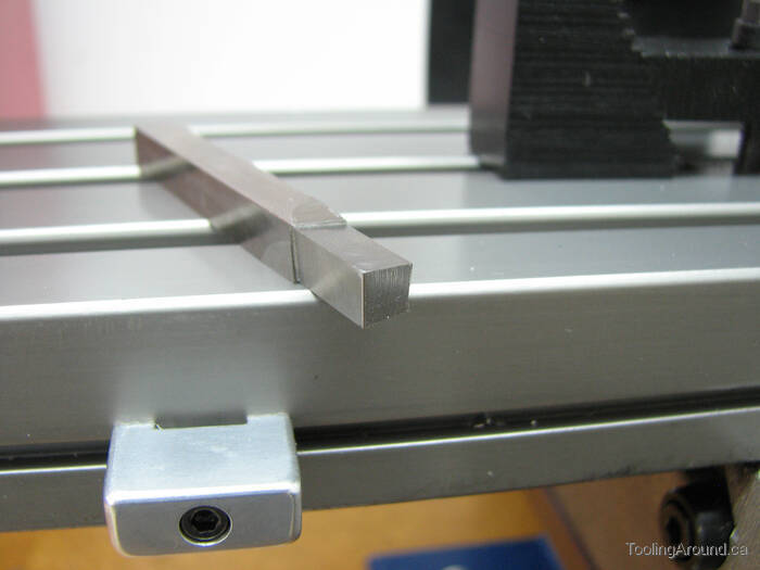
The saw is rotated 7° to get the blank cut at roughly the desired angle. This determines the front relief angle. One of these cut surfaces will be the bottom of the jig and the other will be the top.
For this jig, I used 1.25″×2″ 6061-T1 aluminum bar. As you can see in the photo, it's held narrow side up for the two cuts, which were made a little over 1.75″ apart, to leave room for fly cutting to the correct length. None of these dimensions is critical, so long as your jig is substantial enough to hold the lathe tool securely and so long as the base is large enough to resist tipping over while you're using it.
All surfaces were treated to some attention from the fly cutter.
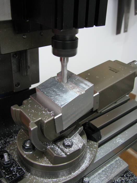
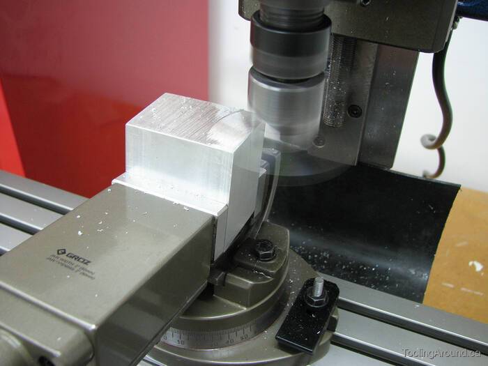
The vise is tilted 7° to mill this slot.
In this photo, the bottom of the jig is against the fixed jaw of the vise. When in use, the bottom of the jig will be sitting on the mill table and the slot floor will be 7° from horizontal. This means that the lathe tool's side rake will be 7°.
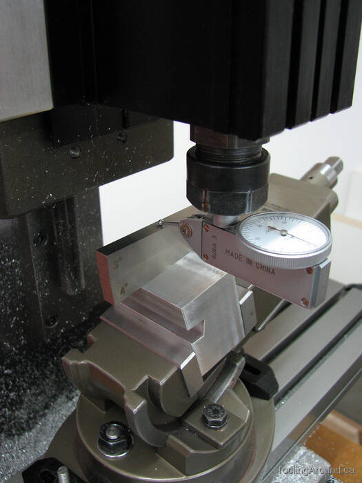
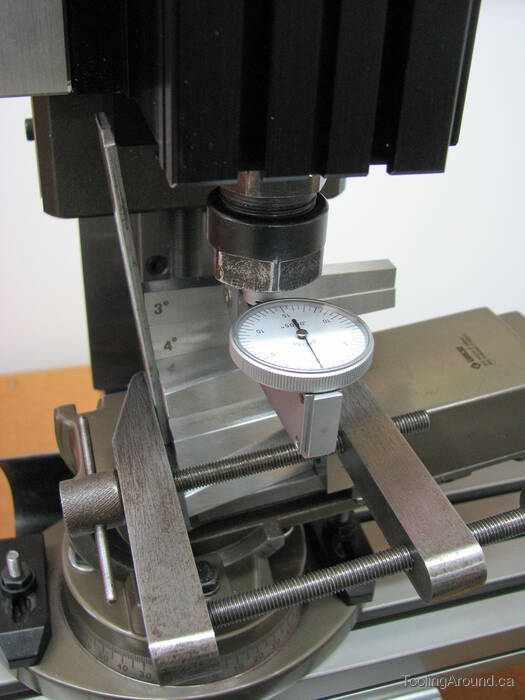
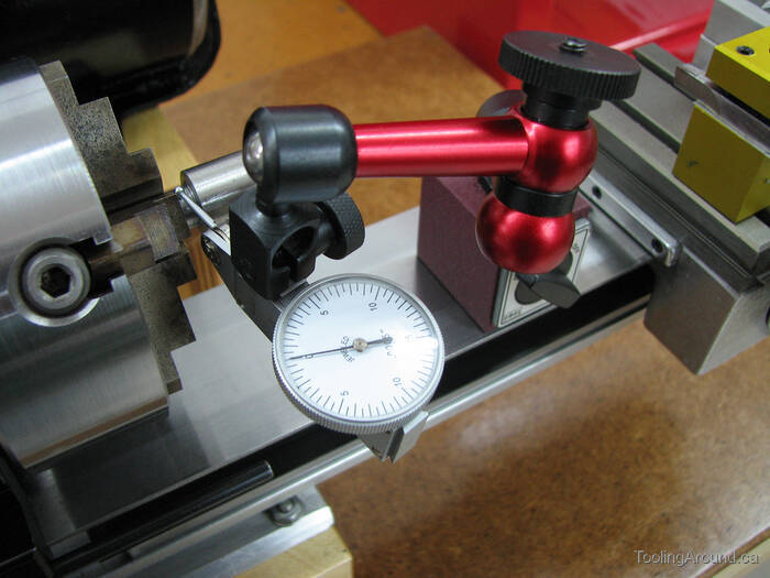
This is how I set the vise to a desired angle, in this case, 7°. Angle blocks are stacked on the work piece and a DTI is used to check that there is no deflection of the needle as the mill table is moved back and forth to slide the indicator's tip along the top of the angle block.
By the way, if you download the plans, you'll note that they show this angle to be 10°, not 7°. I did actually use 10° when I made my jig. Honestly, either value will be fine. My apologies for any confusion on this point.
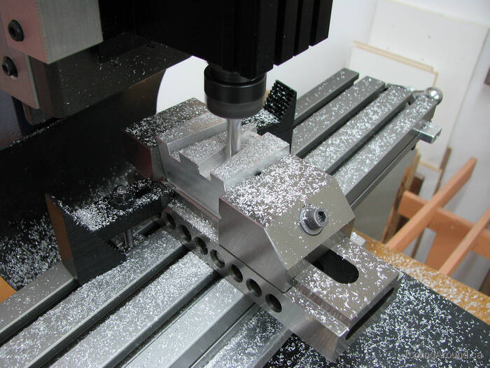
Similarly, I set the angle of the vise to cut slots in the side of the jig. It would be more accurate use a DTI to sweep the edge of the stacked angle blocks, but this is plenty good enough for the application.
This 7° angle determines the tool bit's front rake. In other words, if the tool bit is mounted in the tool post so it's at 90° to the spindle's axis of rotation, when you look directly down at the tool bit from above, the front edge of the tool bit will be at a 7° angle away from the axis of rotation.
Because the entire jig is angled 7° off vertical (remember the angled saw cuts), the front relief angle will be 7°. In other words, if you mount the tool bit as described in the previous paragraph, but view it from the side, instead of the top, the front edge of the tool will be at a 7° angle down and away from the point of contact with the workpiece.
Slots were milled in the sides of the jig.
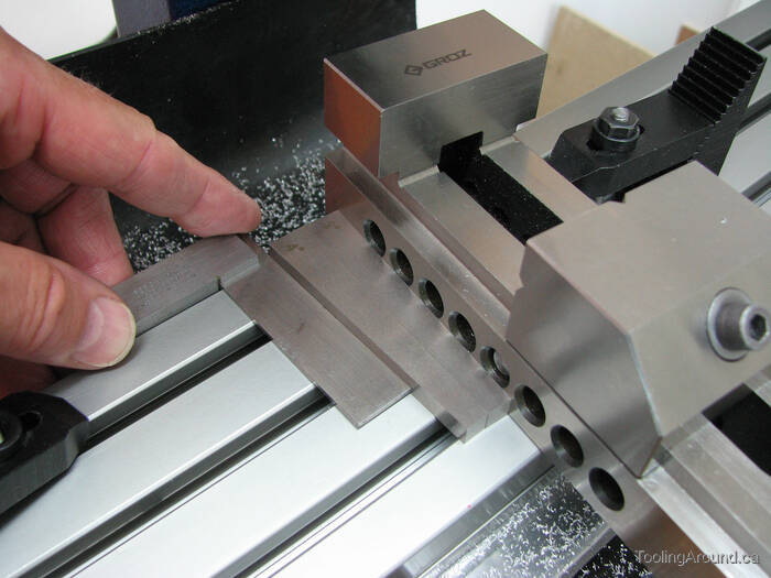
I included this image to show a technique that I've used when the angle blocks want to slide off the work piece. I just clamp a scrap of material to the work piece, to keep them from sliding. It's removed when drilling, of course.
Holes were drilled and tapped for grub screws.
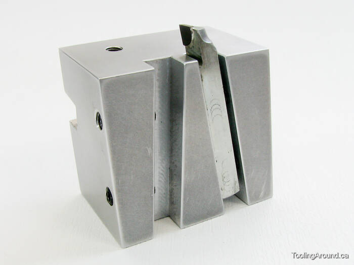
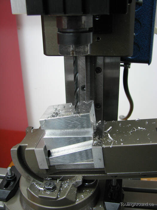
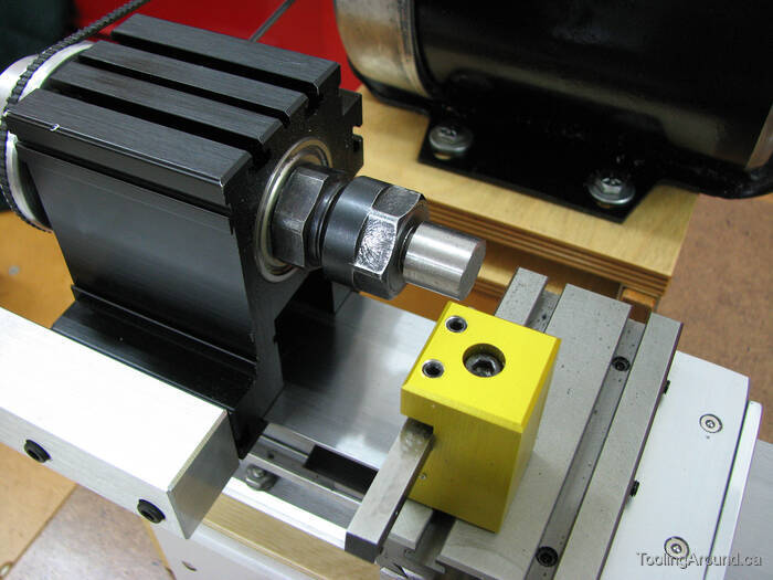
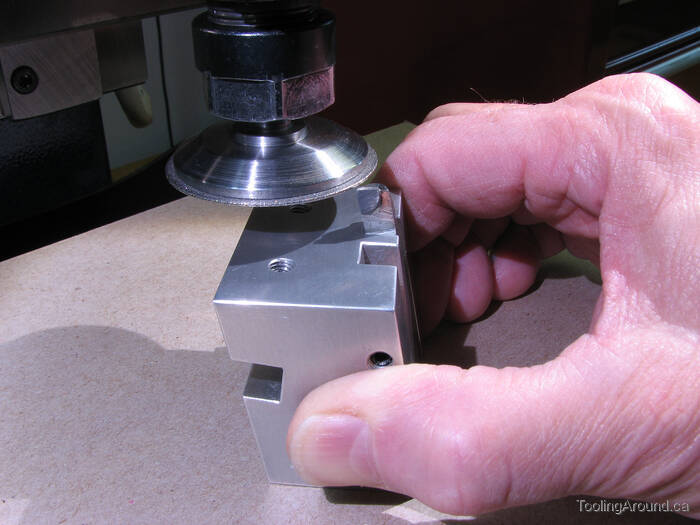
This is the setup for grinding the end of the lathe tool, establishing both the front clearance and rake. Once the top and side angles have been established, this is normally the only surface that needs to be touched up to restore a sharp edge.
In these photos, remember that, as the disk spins in a horizontal plan above the lathe tool, it's the upper-most surface of the tool, as seen in the photo, that will be ground by the disk. I've illustrated the setup using a carbide-tipped tool because it gives a clearer idea of the sharpening operation.
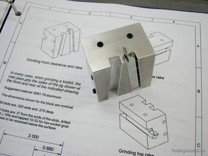
This is how the tool is held to grind the top rake.
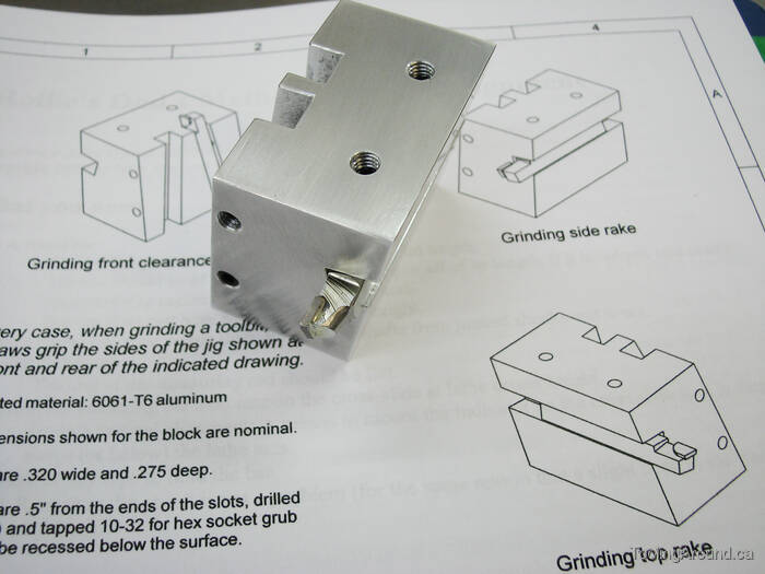
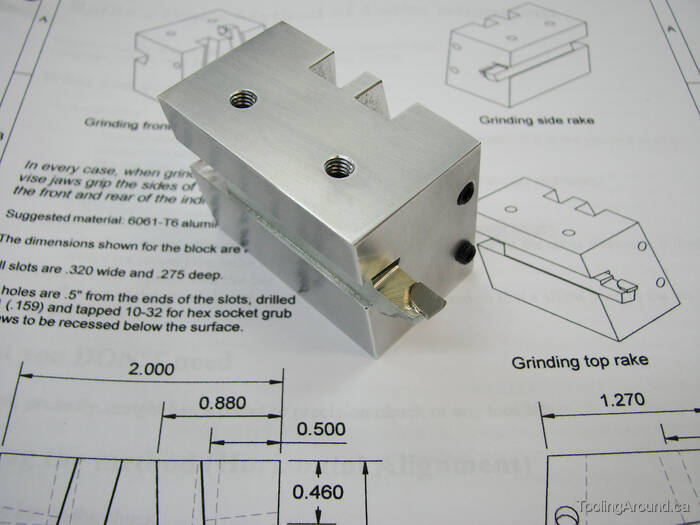
And this is the setup for grinding the side rake.
Wheel Holder (Skip to "Using The Jig".)
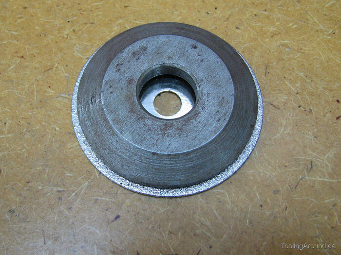
Of course, the jig is useless without something to hold the diamond-coated disk. As it happens, I found this washer in my collection and it looked just right for the job.
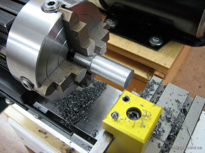
The first step was to turn down part of a short length of 12L14 steel so it would fit in the largest ER-16 collet (i.e. 10mm).
After the shank had been turned, the arbor was reversed in the chuck and centred preparatory to turning the other end.
The other end of the arbor was turned to fit the washer, with a reduced section to fit the hole in the sharpening wheel.
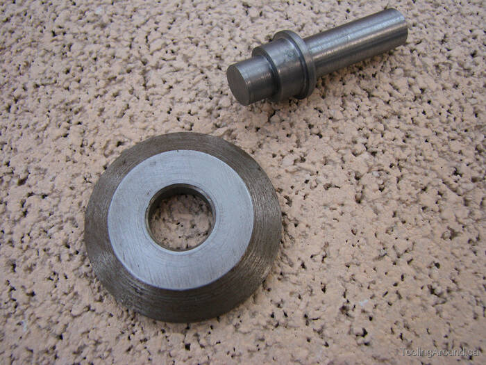
Here is the arbor, ready to be silver brazed to the washer.
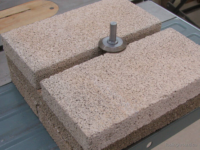
This is typical of the setup I use for silver brazing, using fire bricks to keep the heat away from the surface underneath.
You can tell that this was one of my first attempts at silver brazing. I've used a bit too little flux and far too much brazing material.
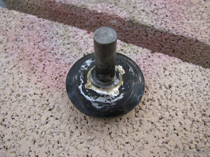
As you can see, there's waste brazing alloy sitting on top of the washer.
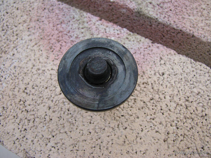
A careful inspection of the other side of the joint shows that the brazing alloy has completely penetrated the joint. However, things are altogether too dirty, mostly because of using too little flux.
Despite the messy appearance in the preceding photos, it cleaned up just fine.
After brazing, I faced the mounting surface for the abrasive disk. Facing after brazing ensures that any slight misalignment of the shaft is corrected.
In the photo, ignore the dark circles. They're just an artifact of the shape of the washer that I used.
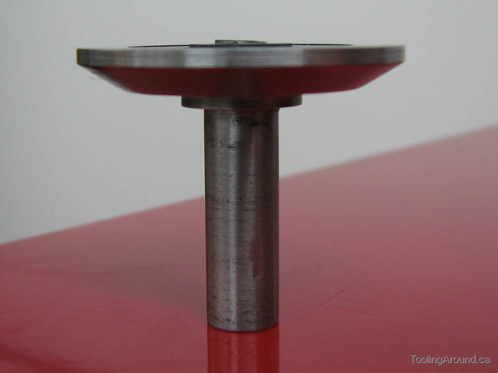
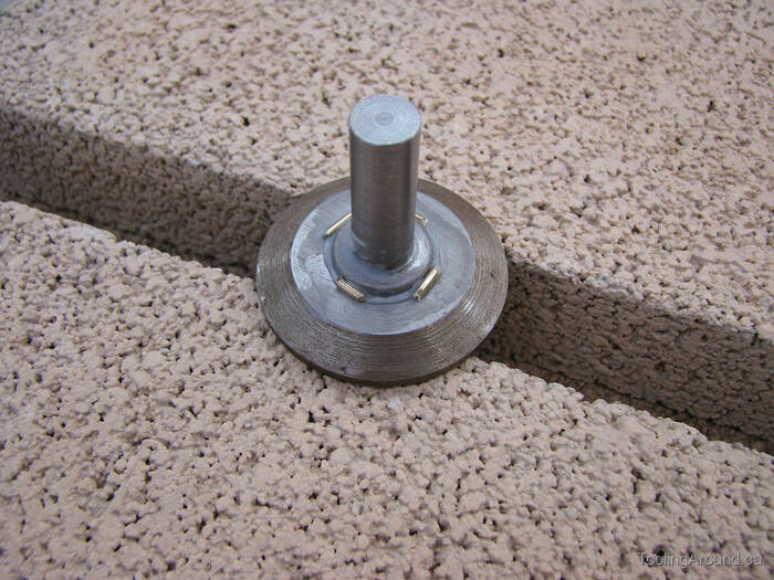
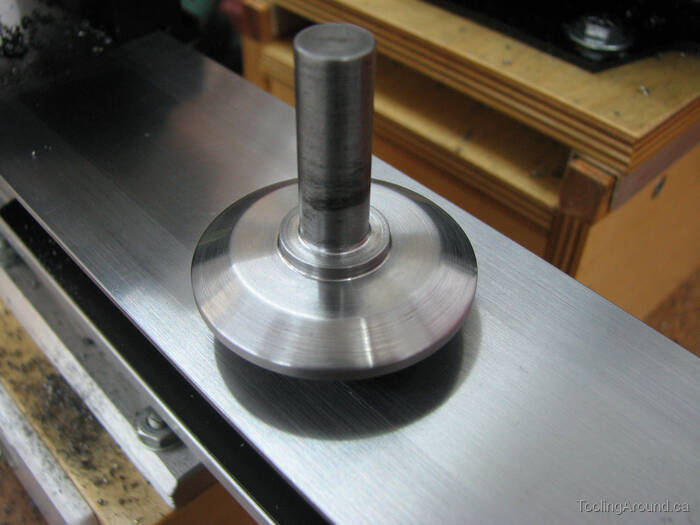
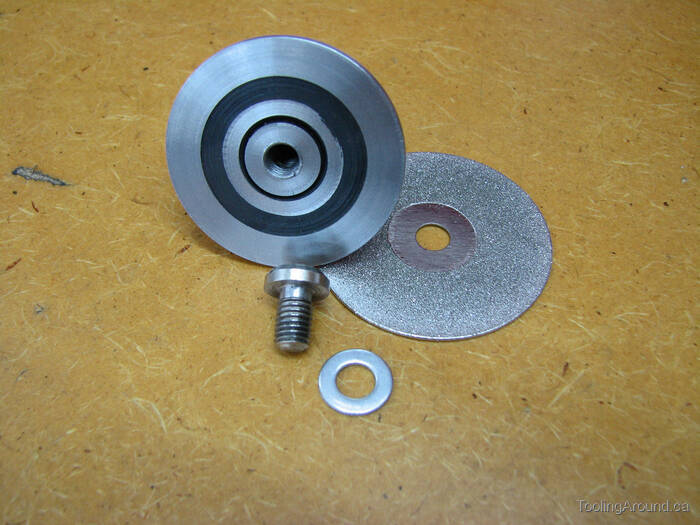
In this profile view of the disk holder, note that the disk will be clamped against the centre portion of the holder, which is raised a bit above the height of the rim. This is to allow for the thickness of the diamond coating, so tightening the mounting screw won't warp the disk. Look at the disk in the previous photo to get an idea of the thickness of the coating.
The even smaller diameter protruding above that mounting surface matches the diameter of the hole in the disk and serves to centre it on the disk holder.
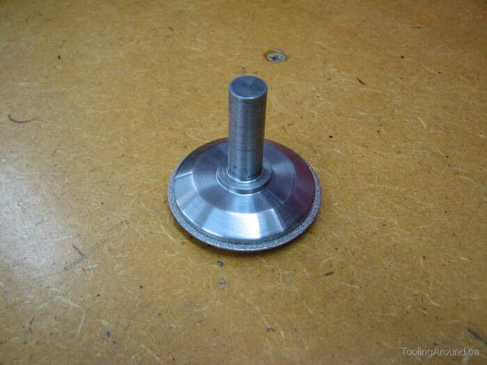
Here's how it looks, ready to use.
Using The Jig
This is how the jig is used to sharpen a tool. In this case, I'm holding it by hand on the mill table. If you prefer, you could mount the jig in a vise and keep your hands clear. Note that I'm just taking a “dusting” of material off the tool, so the forces are minimal. Nevertheless, it pays to keep a firm grip, pressing the jig firmly down against the table.
Unlike the typical abrasive grinding wheel, I've found that this form of sharpening doesn't throw around a little cloud of fine abrasive dust. Instead, I just get a tiny pile of material from the cutting tool. As a precaution against even that getting where you don't want it, you can put a piece of thin cardboard (or paper) under the jig, as shown in the photo. After sharpening, just brush it off into a waste container.
Here's a typical result, after sharpening a HSS tool.
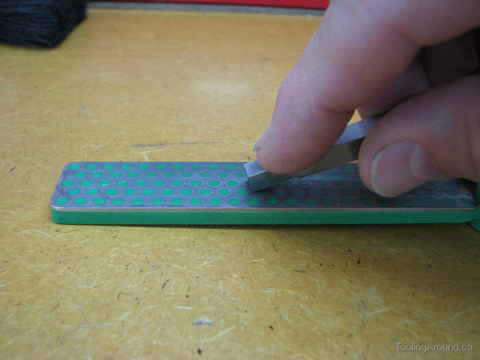
The final step is to very slightly round the vertical edge of the tool. It's really the cutting corner that needs to be given a small radius. This greatly helps you get a fine finish when you use the tool. If you left the corner sharp, you would, in effect, be cutting a very fine thread.
To round off the corner, I actually round off the whole edge, from top to bottom, by drawing it along a diamond-coated surface with a sort of rolling motion. In other words, the tool is in a nearly horizontal position at the start of the motion and ends in a nearly vertical position. It's harder to describe than to do.

Here's a drawing of the jig described on this page.
If I were to make another one, I would put the horizontal slot higher up the side of the jig. It's fine where it is; it's just that the grub screws end up deeper into their holes than necessary.